MCP2140DM-TMPSNS Microchip Technology, MCP2140DM-TMPSNS Datasheet - Page 22
MCP2140DM-TMPSNS
Manufacturer Part Number
MCP2140DM-TMPSNS
Description
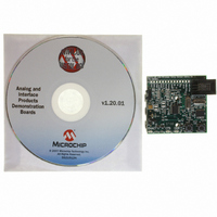
BOARD DEMO FOR MCP2140
Manufacturer
Microchip Technology
Datasheets
1.MCP2140-ISO.pdf
(58 pages)
2.MCP2140-ISO.pdf
(6 pages)
3.MCP2140DM-TMPSNS.pdf
(52 pages)
Specifications of MCP2140DM-TMPSNS
Main Purpose
Interface, IrDA
Embedded
Yes, MCU, 8-Bit
Utilized Ic / Part
MCP2140
Primary Attributes
IrDA Controller with PIC18F MCU and Temp Sensor Temp
Secondary Attributes
Set up as a Data Logger
Processor To Be Evaluated
MCP2140
Interface Type
ICSP
Silicon Manufacturer
Microchip
Silicon Core Number
MCP2140
Kit Application Type
Sensing - Temperature
Application Sub Type
Temperature Sensor
Kit Contents
Board
Rohs Compliant
Yes
Lead Free Status / RoHS Status
Lead free / RoHS Compliant
Lead Free Status / RoHS Status
Lead free / RoHS Compliant, Lead free / RoHS Compliant
Other names
MCP2140DM-TMPSNSR
MCP2140DM-TMPSNSR
MCP2140DM-TMPSNSR
Available stocks
Company
Part Number
Manufacturer
Quantity
Price
Company:

Part Number:
MCP2140DM-TMPSNS
Manufacturer:
Microchip Technology
Quantity:
135
Company:
Part Number:
MCP2140DM-TMPSNS
Manufacturer:
MICROCHIP
Quantity:
12 000


MCP2140 IrDA
DS51487A-page 18
2.4.3.2.2
1. Ensure 3 AAA batteries are properly inserted into the battery holder.
2. Connect JP1 (closed position). The power LED (D5) will turn on. After a few
3. Depress the RESET and S2 buttons, then release the RESET button (keep the
4. Release the S2 button.
5. With both devices on a flat surface, place the MCP2140 IrDA Standard Wireless
6. If the PC is configured to show the IR icon in the system tray, a single IR LED
7. Start the HyperTerminal program by using the saved setting from Section
8. Ensure that the HyperTerminal session indicates “Connected” (lower-left in
9. Place the mouse cursor over the IR icon in the system tray. The message
10. Type any number (0-9) in the HyperTerminal window. The MCP2140 IrDA Stan-
11. The PC HyperTerminal window should receive a string of data about every
12. Device U4 is the TC1047A Temperature Sensor device. The output is connected
13. Disconnect (close) the HyperTerminal session. The DSR and CTS LEDs will
®
Note:
Standard Wireless Temp Sensor Demo Board
seconds, the PHACT LED (D4) will also turn on, indicating that the MCP2140 is
in the NDM (Non-Discovery Mode) state.
S2 button depressed).
Temperature Sensor Demo Board about 25 cm (10”) away from the PC (dark red
window at the front or sides of the PC) toward the two clear LEDs (D1, D6) on
the MCP2140 IrDA Standard Wireless Temperature Sensor Demo Board.
icon will be displayed. Placing the mouse cursor over this icon will display the
message “MCP2140 A5 is in range”, where “MCP2140 A5” is the Device ID of
the MCP2140.
2.4.3.1 “Configuring HyperTerminal”. When HyperTerminal starts, it is in the
connected state. To disconnect, click on the telephone icon (4th icon from left on
toolbar). To connect, click on the telephone icon (3rd icon from left). Depending
on the current state of the HyperTerminal session, only one of the two telephone
icons will be active (the other will be grayed out).
HyperTerminal window) and that the icon in the system tray changes to two IR
LEDs facing each other and “talking”.
displayed now says “Wireless link with MCP2140 A5 at 9600 bps”. This shows
that a link is now established for data communication, and that the IR
communication rate is 9600 bps (even though the HyperTerminal program is
“talking” to the driver at 115200, the IrDA standard hardware is communicating
at the rate negotiated with the MCP2140).
dard Wireless Temperature Sensor Demo Board requires a receive byte before
transmitting it’s data. This is due to the requirement of most PDAs needing to
transmit a data byte before opening the IR Link. The data byte is sent as it is
typed. At this time, the DSR (D2), CTS (D3) and PHACT (D4) LEDs are turned
off.
second. This data string has the format “Temp = xx”, where xx is the measured
temperature in °C.
to an A/D channel of the PIC18F1320. Changing the temperature of this device
will effect the ”temperature” value that is transmitted to the Primary device.
immediately turn off and the PHACT LED will turn on in about 10 seconds.
Temperature value transmitted by the PIC18F1320 will be dependent on
battery voltage (see Section 2.3.2.2 ““Transmit Temperature” Program
Description”).
Operating the “Transmit Temperature” Program
2004 Microchip Technology Inc.
Related parts for MCP2140DM-TMPSNS
Image
Part Number
Description
Manufacturer
Datasheet
Request
R

Part Number:
Description:
IC IRDA CONTROLLR DTE/DCE 18SOIC
Manufacturer:
Microchip Technology
Datasheet:

Part Number:
Description:
The MCP2140 Embeds Irda Protocol Handling And Bit Encoding/decoding, And Provides The Lowest Cost, Lowest Power Consumption Solution For Adding Irda Connectivity to Embedded Systems
Manufacturer:
Microchip Technology, Inc.
Datasheet:

Part Number:
Description:
IC IRDA CONTROLLER DTE/DCE 18DIP
Manufacturer:
Microchip Technology
Datasheet:

Part Number:
Description:
IC IRDA CONTROLLR DTE/DCE 20SSOP
Manufacturer:
Microchip Technology
Datasheet:

Part Number:
Description:
9600 BAUD FIXED SPEED IRDA PROTOCOL HANDLER & BIT ENCODER/DECODER, -40C to +85C, 20-SSOP 208mil, TUBE
Manufacturer:
Microchip Technology
Datasheet:
Part Number:
Description:
IrDA� Standard Protocol Stack Controller With Fixed 9600 Baud Communication Rate
Manufacturer:
MICROCHIP [Microchip Technology]
Datasheet:

Part Number:
Description:
Manufacturer:
Microchip Technology Inc.
Datasheet:
Part Number:
Description:
Manufacturer:
Microchip Technology Inc.
Datasheet:
Part Number:
Description:
Manufacturer:
Microchip Technology Inc.
Datasheet:
Part Number:
Description:
Manufacturer:
Microchip Technology Inc.
Datasheet:
Part Number:
Description:
Manufacturer:
Microchip Technology Inc.
Datasheet:
Part Number:
Description:
Manufacturer:
Microchip Technology Inc.
Datasheet: