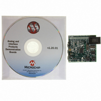
MCP2140DM-TMPSNS Microchip Technology, MCP2140DM-TMPSNS Datasheet - Page 29

MCP2140DM-TMPSNS
Manufacturer Part Number
MCP2140DM-TMPSNS
Description
BOARD DEMO FOR MCP2140
Manufacturer
Microchip Technology
Datasheets
1.MCP2140-ISO.pdf
(58 pages)
2.MCP2140-ISO.pdf
(6 pages)
3.MCP2140DM-TMPSNS.pdf
(52 pages)
Specifications of MCP2140DM-TMPSNS
Main Purpose
Interface, IrDA
Embedded
Yes, MCU, 8-Bit
Utilized Ic / Part
MCP2140
Primary Attributes
IrDA Controller with PIC18F MCU and Temp Sensor Temp
Secondary Attributes
Set up as a Data Logger
Processor To Be Evaluated
MCP2140
Interface Type
ICSP
Silicon Manufacturer
Microchip
Silicon Core Number
MCP2140
Kit Application Type
Sensing - Temperature
Application Sub Type
Temperature Sensor
Kit Contents
Board
Rohs Compliant
Yes
Lead Free Status / RoHS Status
Lead free / RoHS Compliant
Lead Free Status / RoHS Status
Lead free / RoHS Compliant, Lead free / RoHS Compliant
Other names
MCP2140DM-TMPSNSR
MCP2140DM-TMPSNSR
MCP2140DM-TMPSNSR
Available stocks
Company
Part Number
Manufacturer
Quantity
Price
Company:
Part Number:
MCP2140DM-TMPSNS
Manufacturer:
Microchip Technology
Quantity:
135
Company:
Part Number:
MCP2140DM-TMPSNS
Manufacturer:
MICROCHIP
Quantity:
12 000
A.1
A.2
2004 Microchip Technology Inc.
INTRODUCTION
SCHEMATICS AND PCB LAYOUT
This appendix contains the following schematics and layouts for the MCP2140 IrDA
Standard Wireless Temperature Sensor Demo Board:
• Board Schematic - Digital circuitry
• Board Schematic - Analog circuitry
• Board - Top Layer
• Board - Bottom Layer
• Board - Ground Layer
• Board - Power Layer
Figure A-2 shows the schematic of the digital circuitry, while Figure A-3 shows the
analog circuitry for the MCP2140 receiver circuitry and transmitter circuitry.
Figure A-4 through Figure A-7 show the layout for the four different layers of the
MCP2140 IrDA Standard Wireless Temperature Sensor Demo Board. The layer order
is shown in Figure A-1.
FIGURE A-1:
A.2.1
There are 3 ECNs to the Rev. 1 version of the board. Two relate to the use of alternate
optical transceivers and are discussed in Appendix E. “Alternate Optical Transceiver
Implementation”. The third relates to the pinout of transistor Q6 (MMUN2111LT1). An
incorrect pinout was specified, so the device needs to be rotated 1 pin in the clockwise
direction. Figure A-8 shows how this change will appear.
Appendix A. Schematic and Layouts
Electronic Change Notice (ECN)
WIRELESS TEMPERATURE SENSOR
LAYER ORDER
DEMO BOARD USER’S GUIDE
MCP2140 IrDA
Top Layer
Ground Layer
Power Layer
Bottom Layer
®
STANDARD
DS51487A-page 25


