OM6273,598 NXP Semiconductors, OM6273,598 Datasheet
OM6273,598
Specifications of OM6273,598
935283084598


Related parts for OM6273,598


OM6273,598 Summary of contents
Page 1
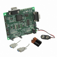
Hardware Connection The hardware connection of SC16IS752/762 in Figure 1 shows the jumpers setting on the SC16IS752/762 demo board and how to connect the demo board to the computers with RS-232 cables. The steps how to connect them are described ...
Page 2
Software Connection Next are the steps how to use the Graphical User Interface (GUI) software in Windows operating system to easily control the SC16IS752/762 demo board from the computer 1. Click on Start -> Programs -> Accessories -> Communications to ...
Page 3
Figure 5. Direct COM4 – HyperTerminal Application Diagram The block diagram in Figure 6 shows a host processor with I2C-bus or SPI-bus interface communicating with the SC16IS752/762 Bridge IC to control the peripherals such as modem, PDA, keypad, etc. Using ...
Page 4
If an IrDA feature is not enabled or used, the host processor can communicate with the UART devices such as remote system, modem, handheld cradle through RS-232 or RS-485 interface. For designs using RS-485 communication, the UART channel of the ...