EVAL6206PD STMicroelectronics, EVAL6206PD Datasheet - Page 4
EVAL6206PD
Manufacturer Part Number
EVAL6206PD
Description
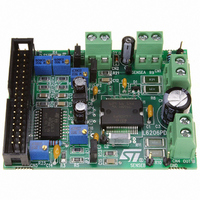
EVAL BOARD FOR L6206 SERIES
Manufacturer
STMicroelectronics
Datasheet
1.L6206N.pdf
(23 pages)
Specifications of EVAL6206PD
Mfg Application Notes
PractiSPIN AppNote
Design Resources
EVAL6206PD/6206PD Gerber Files EVAL6206PD Schematic/Bill of Materials
Main Purpose
Power Management, H Bridge Driver (Internal FET)
Embedded
No
Utilized Ic / Part
L6206
Primary Attributes
2 H-Bridge, 8 ~ 52V Output, Use with PractiSPIN
Secondary Attributes
Temperature Protection, Adjustable Current Limit
Applications
Motor Control
Processor To Be Evaluated
L6206PD
For Use With
497-4138 - EVALUATION BOARD PRACTISPIN
Lead Free Status / RoHS Status
Contains lead / RoHS non-compliant
Other names
497-4135


L6206
PIN DESCRIPTION
4/23
PowerDIP24
SO24/
18, 19
PIN #
6, 7,
10
11
12
13
14
15
16
17
20
21
1
2
3
4
5
8
9
PACKAGE
PowerSO36
19, 36
PIN #
1, 18,
10
11
12
13
15
22
24
25
26
27
28
29
30
32
33
4
5
PROGCL
SENSE
SENSE
VBOOT
OUT1
OUT1
OUT2
OUT2
Name
OCD
OCD
GND
IN1
IN2
IN1
IN2
EN
VS
VS
B
A
B
A
A
B
B
A
B
A
B
B
A
A
B
B
Power Supply
Power Supply
Power Supply
Power Supply
Power Output
Power Output
Power Output
Power Output
Open Drain
Open Drain
Logic Input
Logic Input
Logic Input
Logic input
Logic input
Voltage
Supply
Output
Output
R Pin
Type
GND
Bridge A Logic Input 1.
Bridge A Logic Input 2.
Bridge A Source Pin. This pin must be connected to Power
Ground directly or through a sensing power resistor.
Bridge A Overcurrent Detection and thermal protection pin.
An internal open drain transistor pulls to GND when
overcurrent on bridge A is detected or in case of thermal
protection.
Bridge A Output 1.
Signal Ground terminals. In Power DIP and SO packages,
these pins are also used for heat dissipation toward the
PCB.
Bridge B Output 1.
Bridge B Overcurrent Detection and thermal protection pin.
An internal open drain transistor pulls to GND when
overcurrent on bridge B is detected or in case of thermal
protection.
Bridge B Source Pin. This pin must be connected to Power
Ground directly or through a sensing power resistor.
Bridge B Input 1
Bridge B Input 2
Bridge B Overcurrent Level Programming. A resistor
connected between this pin and Ground sets the
programmable current limiting value for the bridge B. By
connecting this pin to Ground the maximum current is set.
This pin cannot be left non-connected.
Bridge B Enable. LOW logic level switches OFF all Power
MOSFETs of Bridge B.
If not used, it has to be connected to +5V.
Bootstrap Voltage needed for driving the upper Power
MOSFETs of both Bridge A and Bridge B.
Bridge B Output 2.
Bridge B Power Supply Voltage. It must be connected to
the supply voltage together with pin VS
Bridge A Power Supply Voltage. It must be connected to
the supply voltage together with pin VS
Bridge A Output 2.
Function
A
B
.
.
Related parts for EVAL6206PD
Image
Part Number
Description
Manufacturer
Datasheet
Request
R

Part Number:
Description:
ENERCHIP CC EVAL KIT
Manufacturer:
Cymbet Corporation
Datasheet:

Part Number:
Description:
BOARD EVAL FOR AD976
Manufacturer:
Analog Devices Inc
Datasheet:

Part Number:
Description:
BOARD EVAL FOR ADXL345
Manufacturer:
Analog Devices Inc
Datasheet:

Part Number:
Description:
ENERCHIP CC SEH EVAL KIT
Manufacturer:
Cymbet Corporation
Datasheet:

Part Number:
Description:
ENERCHIP EP ENERGY HARVEST EVAL
Manufacturer:
Cymbet Corporation
Datasheet:

Part Number:
Description:
EVAL BOARD FOR TW6864-LB2-GR
Manufacturer:
Intersil
Datasheet:
Part Number:
Description:
EVAL BOARD FOR TW8816-LB3-GR
Manufacturer:
Intersil
Datasheet:
Part Number:
Description:
EVAL BOARD FOR TW8817-TA3-GRS
Manufacturer:
Intersil
Datasheet:

Part Number:
Description:
EVALUATION MODULE FOR ADUM4160
Manufacturer:
Analog Devices Inc
Datasheet:

Part Number:
Description:
BOARD EVALUATION ADCMP581BCP
Manufacturer:
Analog Devices Inc
Datasheet:
Part Number:
Description:
BOARD EVALUATION ADM1041
Manufacturer:
Analog Devices Inc
Datasheet:

Part Number:
Description:
EVAL BOARD FOR STM32F107VCT
Manufacturer:
STMicroelectronics
Datasheet:
Part Number:
Description:
BOARD EVAL FOR AD1954
Manufacturer:
Analog Devices Inc
Datasheet:
Part Number:
Description:
BOARD EVAL FOR AD1955
Manufacturer:
Analog Devices Inc
Datasheet:

Part Number:
Description:
BOARD EVAL FOR AD7655
Manufacturer:
Analog Devices Inc
Datasheet: