KSZ8041NL-EVAL Micrel Inc, KSZ8041NL-EVAL Datasheet - Page 18
KSZ8041NL-EVAL
Manufacturer Part Number
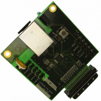
KSZ8041NL-EVAL
Description
BOARD EVALUATION FOR KSZ8041NL
Manufacturer
Micrel Inc
Specifications of KSZ8041NL-EVAL
Main Purpose
Interface, Ethernet PHY
Embedded
No
Utilized Ic / Part
KSZ8041NL
Primary Attributes
Single Chip PHY, 10BASE-T/100BASE-TX
Secondary Attributes
MII, RMII, HP Auto MDI, MDI-X Auto Polarity Correction
Lead Free Status / RoHS Status
Lead free / RoHS Compliant
Other names
576-1621


Notes:
Micrel, Inc.
Pin Description – KSZ8041RNL (Continued)
September 2010
Pin Number
31
32
PADDLE
1.
2.
3.
P = Power supply.
Gnd = Ground.
I = Input.
O = Output.
I/O = Bi-directional.
Opu = Output with internal pull-up (40K +/-30%).
Ipu/O = Input with internal pull-up (40K +/-30%) during power-up/reset; output pin otherwise.
Ipd/O = Input with internal pull-down (40K +/-30%) during power-up/reset; output pin otherwise.
RMII Rx Mode: The RXD[1:0] bits are synchronous with REF_CLK. For each clock period in which CRS_DV is asserted, two bits of
recovered data are sent from the PHY.
RMII Tx Mode: The TXD[1:0] bits are synchronous with REF_CLK. For each clock period in which TX_EN is asserted, two bits of data are
received by the PHY from the MAC.
Pin Name
LED1 /
SPEED
RST#
GND
Type
Ipu/O
Gnd
I
(1)
Pin Function
LED Output:
Config Mode:
The LED1 pin is programmable via register 1Eh bits [15:14], and is defined as
follows.
LED mode = [10], [11]
Chip Reset (active low)
Ground
LED mode = [00]
Speed
10BT
100BT
LED mode = [01]
Activity
No Activity
Activity
Programmable LED1 Output /
Latched as SPEED (register 0h, bit 13) during power-up / reset.
See “Strapping Options” section for details.
Pin State
Toggle
Pin State
H
L
H
18
Reserved
LED Definition
OFF
ON
LED Definition
Blinking
OFF
M9999-090910-1.4
KSZ8041NL/RNL
Related parts for KSZ8041NL-EVAL
Image
Part Number
Description
Manufacturer
Datasheet
Request
R

Part Number:
Description:
IC TXRX PHY 10/100 LV/LP 32-MLF
Manufacturer:
Micrel Inc
Datasheet:
Part Number:
Description:
Physical Layer Transceiver 10/100BASE-T/TX ( ) - Automotive Qualified
Manufacturer:
Micrel Inc
Datasheet:

Part Number:
Description:
Physical Layer Transceiver 10/100BASE-T/TX ( ) - Automotive Qualified
Manufacturer:
Micrel Inc
Datasheet:

Part Number:
Description:
Manufacturer:
Micrel Inc
Datasheet:
Part Number:
Description:
Manufacturer:
Micrel Inc
Datasheet:
Part Number:
Description:
Manufacturer:
Micrel Inc
Datasheet:
Part Number:
Description:
Manufacturer:
Micrel Inc
Datasheet:
Part Number:
Description:
Manufacturer:
Micrel Inc
Datasheet:
Part Number:
Description:
Manufacturer:
Micrel Inc
Datasheet:
Part Number:
Description:
Manufacturer:
Micrel Inc
Datasheet:
Part Number:
Description:
Manufacturer:
Micrel Inc
Datasheet:
Part Number:
Description:
Manufacturer:
Micrel Inc
Datasheet:
Part Number:
Description:
Manufacturer:
Micrel Inc
Datasheet: