KSZ8041NL-EVAL Micrel Inc, KSZ8041NL-EVAL Datasheet - Page 30
KSZ8041NL-EVAL
Manufacturer Part Number
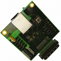
KSZ8041NL-EVAL
Description
BOARD EVALUATION FOR KSZ8041NL
Manufacturer
Micrel Inc
Specifications of KSZ8041NL-EVAL
Main Purpose
Interface, Ethernet PHY
Embedded
No
Utilized Ic / Part
KSZ8041NL
Primary Attributes
Single Chip PHY, 10BASE-T/100BASE-TX
Secondary Attributes
MII, RMII, HP Auto MDI, MDI-X Auto Polarity Correction
Lead Free Status / RoHS Status
Lead free / RoHS Compliant
Other names
576-1621


Micrel, Inc.
KSZ8041NL/RNL
Power Management
The KSZ8041NL/RNL offers the following power management modes:
Power Saving Mode
This mode is used to reduce power consumption when the cable is unplugged. It is in effect when auto-negotiation mode
is enabled, cable is disconnected, and register 1F bit 10 is set to 1. Under power saving mode, the KSZ8041NL/RNL
shuts down all transceiver blocks, except for transmitter, energy detect and PLL circuits. Additionally, for the KSZ8041NL
in MII mode, the RXC clock output is disabled. RXC clock is enabled after the cable is connected and link is established.
Power saving mode is disabled by writing a zero to register 1F bit 10.
Power Down Mode
This mode is used to power down the entire KSZ8041NL/RNL device when it is not in use. Power down mode is enabled
by writing a one to register 0 bit 11. In the power down state, the KSZ8041NL/RNL disables all internal functions, except
for the MII management interface.
Reference Clock Connection Options
A crystal or clock source, such as an oscillator, is used to provide the reference clock for the KSZ8041NL/RNL.
The Figure 6 illustrates how to connect the 25MHz crystal and oscillator reference clock.
Figure 6. 25MHz Crystal / Oscillator Reference Clock
For the KSZ8041NL, Figure 7 illustrates how to connect the 50MHz oscillator reference clock for RMII mode.
Figure 7. 50MHz Oscillator Reference Clock for KSZ8041NL RMII Mode
September 2010
30
M9999-090910-1.4
Related parts for KSZ8041NL-EVAL
Image
Part Number
Description
Manufacturer
Datasheet
Request
R

Part Number:
Description:
IC TXRX PHY 10/100 LV/LP 32-MLF
Manufacturer:
Micrel Inc
Datasheet:
Part Number:
Description:
Physical Layer Transceiver 10/100BASE-T/TX ( ) - Automotive Qualified
Manufacturer:
Micrel Inc
Datasheet:

Part Number:
Description:
Physical Layer Transceiver 10/100BASE-T/TX ( ) - Automotive Qualified
Manufacturer:
Micrel Inc
Datasheet:

Part Number:
Description:
Manufacturer:
Micrel Inc
Datasheet:
Part Number:
Description:
Manufacturer:
Micrel Inc
Datasheet:
Part Number:
Description:
Manufacturer:
Micrel Inc
Datasheet:
Part Number:
Description:
Manufacturer:
Micrel Inc
Datasheet:
Part Number:
Description:
Manufacturer:
Micrel Inc
Datasheet:
Part Number:
Description:
Manufacturer:
Micrel Inc
Datasheet:
Part Number:
Description:
Manufacturer:
Micrel Inc
Datasheet:
Part Number:
Description:
Manufacturer:
Micrel Inc
Datasheet:
Part Number:
Description:
Manufacturer:
Micrel Inc
Datasheet:
Part Number:
Description:
Manufacturer:
Micrel Inc
Datasheet: