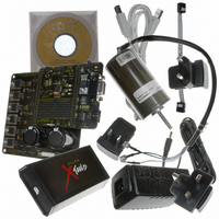
Z8FMC160100KIT Zilog, Z8FMC160100KIT Datasheet - Page 5

Z8FMC160100KIT
Manufacturer Part Number
Z8FMC160100KIT
Description
KIT DEV FOR Z8 ENCORE Z8FMC16100
Manufacturer
Zilog
Series
Z8 Encore! MC™r
Datasheets
1.Z8FMC160100KIT.pdf
(7 pages)
2.Z8FMC160100KIT.pdf
(383 pages)
3.Z8FMC160100KIT.pdf
(20 pages)
Specifications of Z8FMC160100KIT
Main Purpose
Power Management, Motor Control
Embedded
Yes, MCU, 8-Bit
Utilized Ic / Part
Z8FMC16100
Primary Attributes
3-Ph DC Motors
Secondary Attributes
Graphic User Interface
Processor To Be Evaluated
Z8FMC16100
Data Bus Width
8 bit
Interface Type
USB
For Use With
269-4664 - KIT ACC OPTO-ISO USB SMART CABLE269-4661 - KIT ACC ETHERNET SMART CABLE269-4539 - KIT ACCESSORY USB SMART CABLE
Lead Free Status / RoHS Status
Contains lead / RoHS non-compliant
Other names
269-3639
that the highest interrupt priority is assigned to the Back EMF sensing event, as this is a critical step for
subsequent synchronization of the commutation events. In this case, Timer 0 is used for the Time Stamp
function as well as for updating the commutation period if necessary.
Hardware Architecture
Figure 1
Controller. This block diagram can be divided into the Control Section and the Power Conversion section.
In the Control Section, the Z8FMC16100 MCU is operating with an external 20-Mhz crystal.
a list of pins being used in the Z8FMC16100 MCU along with the associated use in this design.
Pin No.
AN022602-0810
10
11
12
13
14
15
16
17
18
19
20
21
22
23
24
25
26
27
28
29
30
31
32
1
2
3
4
5
6
7
8
9
on page 4 displays the functional block diagram of the Z8 Encore! MC™ Sensorless Brushless Motor
Pin Description
PB2/ANA2/TOIN2
PB1/ANA1/TOIN1
PB0/ANA0/TOIN0
AVVD
AVVS
VREF
PA0/OPINN
PA1/OPINP/CINN
PA2/CINP
PA7/FAULT1/T0OUT…
RESET/FAULT0
DBG
PC0/T0OUT
PWML2
PWMH2
PWML1
PWMH1
PWML0
PWMH0
VSS
XOUT
XIN
VDD
PA3/TXDE/SCK/SCL
PA4/RXD/MISO
PA5/TXD/MOSI
PA6/CTS/SS/SDA
PB7/ANA7
PB6/ANA6
PB5/ANA5
PB4/ANA4/CINN
PB3/ANA3/OPOUT
Sensorless Brushless DC Motor Control with Z8 Encore! MC
Function
ANA2
ANA1
ANA0
AVVD
AVVS
VREF
OPINN
OPINP
CINP
PA7
RESET
DBG
PC0
PWML2
PWMH2
PWML1
PWMH1
PWML0
PWMH0
VSS
XOUT
XIN
VDD
PA3
RXD
TXD
CTS
PB7
ANA6
ANA5
ANA4
ANA3
Table 1. Pin Function Descriptions
In/Out/PWR
Input
Input
Input
PWR
PWR
PWR
Input
Input
Input
Output
Input
Input/Output
Input
Output
Output
Output
Output
Output
Output
PWR
Output
Input
PWR
Output
Input
Output
Input
Output
Input
Output
Input
Input
Application Use
Phase C BEMF
Phase B BEMF
Phase A BEMF
3.3V Supply
Ground
Voltage Reference
Current Sense
Current Sense
Current Sense
Fault(Red) LED
STOP/RESET
DEBUG
Direction
Phase C Gate Low
Phase C Gate High
Phase B Gate Low
Phase B Gate High
Phase A Gate Low
Phase A Gate High
Ground
Clock
Clock
3.3V Supply
Power(Yellow) LED
UART Receive
UART Transmit
UART Clear
Run(Green) LED
Speed
ISR Test Pin
DC Bus Voltage
Current Sense
TM
Microcontrollers
Table 1
provides


