Z8FMC160100KIT Zilog, Z8FMC160100KIT Datasheet - Page 7
Z8FMC160100KIT
Manufacturer Part Number
Z8FMC160100KIT
Description
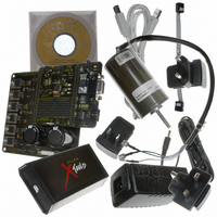
KIT DEV FOR Z8 ENCORE Z8FMC16100
Manufacturer
Zilog
Series
Z8 Encore! MC™r
Datasheets
1.Z8FMC160100KIT.pdf
(7 pages)
2.Z8FMC160100KIT.pdf
(383 pages)
3.Z8FMC160100KIT.pdf
(20 pages)
Specifications of Z8FMC160100KIT
Main Purpose
Power Management, Motor Control
Embedded
Yes, MCU, 8-Bit
Utilized Ic / Part
Z8FMC16100
Primary Attributes
3-Ph DC Motors
Secondary Attributes
Graphic User Interface
Processor To Be Evaluated
Z8FMC16100
Data Bus Width
8 bit
Interface Type
USB
For Use With
269-4664 - KIT ACC OPTO-ISO USB SMART CABLE269-4661 - KIT ACC ETHERNET SMART CABLE269-4539 - KIT ACCESSORY USB SMART CABLE
Lead Free Status / RoHS Status
Contains lead / RoHS non-compliant
Other names
269-3639


TM
Sensorless Brushless DC Motor Control with Z8 Encore! MC
Microcontrollers
load, breakdowns or misfiring of power devices, and many other problems can arise, some of them permanent,
some merely temporary. Whatever may be the origin of an overcurrent condition, motor rotation must be
halted. In this scenario, fast response time is a key criteria for the design of the fault protection system.
However, rather than triggering a hard shutdown of the entire system when a fault is detected, it is better to
disable the motor drive outputs on a cycle-by-cycle basis, with normal operation resuming once the fault
condition is no longer detected. In this case, if the overcurrent condition persists, a hard shutdown then ensues.
Motor control microcontrollers typically incorporate input elements (such as a comparator) for sensing
overcurrent conditions. In many cases, the current signal is routed to the ADC. This approach has a major
drawback due to the excess time associated with data processing before the outcome can disable the PWM.
The resulting data processing latency could in turn delay system shutdown beyond the next switching cycle,
and catastrophic damage could result.
In the Z8 Encore! MC™ family of Microcontrollers, in order to avoid the processing delay inherent with an
ADC, an overcurrent comparator is directly coupled to the PWM module, thereby guaranteeing that the
shutdown can truly occur in a cycle-by-cycle mode. This approach not only improves the controller’s fault
response characteristics, but also circumvents a vulnerability that is inherent with the conventional approach.
Namely, if the MCUs clock were to stop functioning, there would be no risk of accomplishing a shutdown in
response to an overcurrent fault as there would be if the system’s ADC were involved.
All the algorithms have been developed in C using the Zilog ZDS II Integrated Development Environment for
®
the Z8 Encore!
family of products.
Figure 2
shows the main control loop.
Figure 2. Initialization and Application Code Space
This implementation provides precise control of the motor while leaving sufficient resources for additional
application code. Even when using a very small and cost-effective 8-bit MCU, an additional 13 KB of Flash
and 420 bytes of RAM are available for additional user application code.
The Phase Lock Loop Back EMF sensing is unique to this implementation. The details of the algorithm are
described in the following figures and tables. The Back EMF sensing loop is shown in
Figure 3
on page 8.
AN022602-0810
Related parts for Z8FMC160100KIT
Image
Part Number
Description
Manufacturer
Datasheet
Request
R

Part Number:
Description:
Communication Controllers, ZILOG INTELLIGENT PERIPHERAL CONTROLLER (ZIP)
Manufacturer:
Zilog, Inc.
Datasheet:

Part Number:
Description:
KIT DEV FOR Z8 ENCORE 16K TO 64K
Manufacturer:
Zilog
Datasheet:

Part Number:
Description:
KIT DEV Z8 ENCORE XP 28-PIN
Manufacturer:
Zilog
Datasheet:

Part Number:
Description:
DEV KIT FOR Z8 ENCORE 8K/4K
Manufacturer:
Zilog
Datasheet:

Part Number:
Description:
KIT DEV Z8 ENCORE XP 28-PIN
Manufacturer:
Zilog
Datasheet:

Part Number:
Description:
DEV KIT FOR Z8 ENCORE 4K TO 8K
Manufacturer:
Zilog
Datasheet:
Part Number:
Description:
CMOS Z8 microcontroller. ROM 16 Kbytes, RAM 256 bytes, speed 16 MHz, 32 lines I/O, 3.0V to 5.5V
Manufacturer:
Zilog, Inc.
Datasheet:
Part Number:
Description:
Low-cost microcontroller. 512 bytes ROM, 61 bytes RAM, 8 MHz
Manufacturer:
Zilog, Inc.
Datasheet:
Part Number:
Description:
Z8 4K OTP Microcontroller
Manufacturer:
Zilog, Inc.
Datasheet:
Part Number:
Description:
CMOS SUPER8 ROMLESS MCU
Manufacturer:
Zilog, Inc.
Datasheet:
Part Number:
Description:
SL1866 CMOSZ8 OTP Microcontroller
Manufacturer:
Zilog, Inc.
Datasheet:
Part Number:
Description:
SL1866 CMOSZ8 OTP Microcontroller
Manufacturer:
Zilog, Inc.
Datasheet:
Part Number:
Description:
OTP (KB) = 1, RAM = 125, Speed = 12, I/O = 14, 8-bit Timers = 2, Comm Interfaces Other Features = Por, LV Protect, Voltage = 4.5-5.5V
Manufacturer:
Zilog, Inc.
Datasheet:
Part Number:
Description:
Manufacturer:
Zilog, Inc.
Datasheet: