Z8FMC160100KIT Zilog, Z8FMC160100KIT Datasheet - Page 6
Z8FMC160100KIT
Manufacturer Part Number
Z8FMC160100KIT
Description
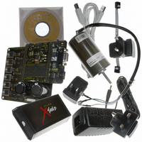
KIT DEV FOR Z8 ENCORE Z8FMC16100
Manufacturer
Zilog
Series
Z8 Encore! MC™r
Datasheets
1.Z8FMC160100KIT.pdf
(7 pages)
2.Z8FMC160100KIT.pdf
(383 pages)
3.Z8FMC160100KIT.pdf
(20 pages)
Specifications of Z8FMC160100KIT
Main Purpose
Power Management, Motor Control
Embedded
Yes, MCU, 8-Bit
Utilized Ic / Part
Z8FMC16100
Primary Attributes
3-Ph DC Motors
Secondary Attributes
Graphic User Interface
Processor To Be Evaluated
Z8FMC16100
Data Bus Width
8 bit
Interface Type
USB
For Use With
269-4664 - KIT ACC OPTO-ISO USB SMART CABLE269-4661 - KIT ACC ETHERNET SMART CABLE269-4539 - KIT ACCESSORY USB SMART CABLE
Lead Free Status / RoHS Status
Contains lead / RoHS non-compliant
Other names
269-3639


TM
Sensorless Brushless DC Motor Control with Z8 Encore! MC
Microcontrollers
The Power Conversion section contains the DC Bus, Gate Drivers, MOSFETs, Power Supply, BEMF dividers,
and temperature sensor. The MOSFETs used in this design are IXYS high-efficient trench gate power
technology. To control the small 30-W BLDC motor, part number IXTP64N055T was selected. However, this
design is scalable to meet the needs of the majority of 3-Phase BLDC motors from 1 W to 5 kW. To support
larger motors, the major design changes are in the Power Conversion section, which include the fuse and the
MOSFETs. The IXYS family of power MOSFETs, which includes both discrete and modules, come in a wide
variety of packages in order to meet the specific mechanical requirements of the application. They also come
in a wide range of power ratings and can support in excess of 500 A.
Software Architecture
The Z8 Encore! MC™ family of Microcontrollers has up to 16 KB of FLASH memory and is based on Zilog’s
advanced eZ8 8-bit CPU core, providing for closed loop control of single- and multiphase variable speed
motors. Target applications are major appliances, HVAC, industrial automation, and consumer electronics. In
each of the Z8 Encore! MC™ products, the novel device architecture allows for the realization of a number of
enhanced control features including Time Stamp for Speed Control, Integrated Operational Amplifier, and
Fault Response.
Time Stamp for Speed Control
Most microcontrollers use at least one dedicated comparator to detect the zero crossing of the input AC voltage
signal, so that the output driving pulses can be synchronized and adjusted to properly regulate the motor speed.
An alternative approach based on Zilog’s motor control MCU eliminates the need for this comparator by
instead employing an ADC in conjunction with a timer. In this case, the ADC samples the AC line voltage,
with the timer running in the background.
After the ADC samples the line voltage zero crossing, the timer count is read, and the result is written to a
register. This in turn cues the timers for the output PWM pulses to efficiently regulate the speed of the motor.
The Time Stamp approach results in a very simple and cost-effective solution for the smooth operation of the
motor in steady state.
Integrated Operational Amplifier
Motor controllers almost invariably monitor motor speed by sensing the current through the windings, using
sensor and sensorless techniques in conjunction with the ADC. Ordinarily, sampling instances by the ADC are
synchronized by the MCU.
In this process, an operational amplifier is used to convert the current signal to a voltage signal, respectively.
The ADC in turn samples the voltage signal and outputs the result to the processor. The processor will then
synthesize the PWM outputs to control motor speed.
In the case of the Z8 Encore! MC™ family of Microcontrollers, an on-chip integrated operational amplifier
eliminates the need for an external component, hence reducing the overall system cost.
Fault Response
Overcurrent faults can result from many different causes and are sometimes destructive. Shorted motor
windings, shorted motor leads, problems in mechanical drives and linkages, a stuck rotor or changes in the
AN022602-0810
Page 6 of 20
Related parts for Z8FMC160100KIT
Image
Part Number
Description
Manufacturer
Datasheet
Request
R

Part Number:
Description:
Communication Controllers, ZILOG INTELLIGENT PERIPHERAL CONTROLLER (ZIP)
Manufacturer:
Zilog, Inc.
Datasheet:

Part Number:
Description:
KIT DEV FOR Z8 ENCORE 16K TO 64K
Manufacturer:
Zilog
Datasheet:

Part Number:
Description:
KIT DEV Z8 ENCORE XP 28-PIN
Manufacturer:
Zilog
Datasheet:

Part Number:
Description:
DEV KIT FOR Z8 ENCORE 8K/4K
Manufacturer:
Zilog
Datasheet:

Part Number:
Description:
KIT DEV Z8 ENCORE XP 28-PIN
Manufacturer:
Zilog
Datasheet:

Part Number:
Description:
DEV KIT FOR Z8 ENCORE 4K TO 8K
Manufacturer:
Zilog
Datasheet:
Part Number:
Description:
CMOS Z8 microcontroller. ROM 16 Kbytes, RAM 256 bytes, speed 16 MHz, 32 lines I/O, 3.0V to 5.5V
Manufacturer:
Zilog, Inc.
Datasheet:
Part Number:
Description:
Low-cost microcontroller. 512 bytes ROM, 61 bytes RAM, 8 MHz
Manufacturer:
Zilog, Inc.
Datasheet:
Part Number:
Description:
Z8 4K OTP Microcontroller
Manufacturer:
Zilog, Inc.
Datasheet:
Part Number:
Description:
CMOS SUPER8 ROMLESS MCU
Manufacturer:
Zilog, Inc.
Datasheet:
Part Number:
Description:
SL1866 CMOSZ8 OTP Microcontroller
Manufacturer:
Zilog, Inc.
Datasheet:
Part Number:
Description:
SL1866 CMOSZ8 OTP Microcontroller
Manufacturer:
Zilog, Inc.
Datasheet:
Part Number:
Description:
OTP (KB) = 1, RAM = 125, Speed = 12, I/O = 14, 8-bit Timers = 2, Comm Interfaces Other Features = Por, LV Protect, Voltage = 4.5-5.5V
Manufacturer:
Zilog, Inc.
Datasheet:
Part Number:
Description:
Manufacturer:
Zilog, Inc.
Datasheet: