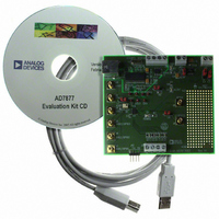
EVAL-AD7877EBZ Analog Devices Inc, EVAL-AD7877EBZ Datasheet - Page 2

EVAL-AD7877EBZ
Manufacturer Part Number
EVAL-AD7877EBZ
Description
BOARD EVALUATION FOR AD7877
Manufacturer
Analog Devices Inc
Datasheets
1.AD7877ACBZ-REEL7.pdf
(44 pages)
2.EVAL-AD7877EBZ.pdf
(16 pages)
3.EVAL-AD7877EBZ.pdf
(44 pages)
Specifications of EVAL-AD7877EBZ
Main Purpose
Interface, Touch Screen Controller
Embedded
No
Utilized Ic / Part
AD7877
Primary Attributes
4-Wire Resistive Touch Screen Controller, SPI Interface, On-Chip: Temp Sensor, Voltage Reference, 8-Bit DAC
Secondary Attributes
USB GUI, LCD Noise Reduction Feature, 2.7 ~ 5.25 V, Wake Up on Touch Feature
Lead Free Status / RoHS Status
Lead free / RoHS Compliant
EVAL-AD7877
Number
J15
J14
J13
J12
J11
J10
J9
J8
J7
J6
TO USB
CONNECTOR
R
MAX
REGULATOR
= 2k
VOLTAGE
Name
V
USB Interface
Power
Touch Screen
A
USB IC Interface
STOPACQ
GPIO4
AUX1/GPIO1
AUX2/GPIO2
J13-1
REF
OUT
R
VAR
and V
LK1
LK5
DRIVE
3.3V
J15-1
B
A
B
A
LK4
Figure 1. AD7877 Evaluation Board Block Diagram
TEST POINT
B
A
CONNECTOR FUNCTION DESCRIPTIONS
J12-2
VBAT2
VBAT1
AUX3/GPIO3
AUX2/GPIO2
AUX1/GPIO1
V
CC
Description
These screw-top connectors can be used to supply V
To supply an external V
to J15-1. To supply an external V
signal applied to J15-2.
The USB cable should be plugged directly from the PC into this connector. It is a
type B USB socket.
Power can be supplied to the board either via the USB cable or via the power connec-
tor J13. If Link 5 is in Position B, power is supplied via the USB cable. If Link 5 is in
Position A, power is supplied from the J13 connector.
The MicroTouch touch screen included with the demonstration kit can be connected
directly into the AD7877 demonstration board using this connector. Connections are
as follows: X+ to J12-1, X– to J12-2, Y+ to J12-3, and Y– to J12-4.
This subminiature BNC socket can be used to access the A
AD7877.
The USB controller IC has an I
SDA is available on J10-1, SCL is available on J10-2, GND is available on J10-3, and
3.3 V is available on J10-4.
This subminiature BNC socket can be used to apply a signal to the STOPACQ input
on the AD7877. If Link 6 is in Position B, the signal applied to J9 goes directly to the
STOPACQ pin. If Link 6 is in Position A, STOPACQ is tied to GND.
This subminiature BNC socket can be used to apply a signal to the GPIO4 input on
the AD7877.
This subminiature BNC socket can be used to apply a signal to the AUX1/GPIO1
input on the AD7877.
This subminiature BNC socket can be used to apply a signal to the AUX2/GPIO2
input on the AD7877.
J2-1
X–
J12-4
A
J2-2
Y–
OPTIONAL
LK3
AD7877
J12-1
R-C
B
R
J2-3
X+
RNG
J12-3
B
A
–2–
J2-4
STOPACQ
Y+
LK2
PENIRQ
ALERT
GPIO4
REF
DAV
DIN
CS
, Link 4 should be in the B position, and the signal applied
3.3V
J15-2
TEST POINTS
2
C interface that can be accessed using this connector.
DRIVE
TEST POINTS
, Link 2 should be in the B position, and the
3.3V
3.3V
MICROCONTROLLER
REF
CY7C68013
EEPROM
and V
USB
OUT
DRIVE
output signal from the
to the AD7877.
TO USB
CONNECTOR
REV. Sp0


