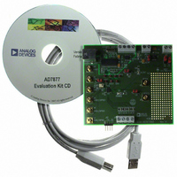
EVAL-AD7877EBZ Analog Devices Inc, EVAL-AD7877EBZ Datasheet - Page 8

EVAL-AD7877EBZ
Manufacturer Part Number
EVAL-AD7877EBZ
Description
BOARD EVALUATION FOR AD7877
Manufacturer
Analog Devices Inc
Datasheets
1.AD7877ACBZ-REEL7.pdf
(44 pages)
2.EVAL-AD7877EBZ.pdf
(16 pages)
3.EVAL-AD7877EBZ.pdf
(44 pages)
Specifications of EVAL-AD7877EBZ
Main Purpose
Interface, Touch Screen Controller
Embedded
No
Utilized Ic / Part
AD7877
Primary Attributes
4-Wire Resistive Touch Screen Controller, SPI Interface, On-Chip: Temp Sensor, Voltage Reference, 8-Bit DAC
Secondary Attributes
USB GUI, LCD Noise Reduction Feature, 2.7 ~ 5.25 V, Wake Up on Touch Feature
Lead Free Status / RoHS Status
Lead free / RoHS Compliant
EVAL-AD7877
Log Data
Clicking on the Log Data button opens the window in Figure 8.
The user can choose the data to be logged to an Excel file by
clicking the relevant boxes. The voltage measurements, the
touch screen inputs, and the temperature results can all be
logged to a file. The interval at which data is logged can also be
chosen. On pressing the OK button, the user can open an Excel
file, where the data is logged.
Figure 8. Log Data Screen
Figure 7. Visual Display Screen: Touch Screen Coordinates
–8–
Easy Setup
Clicking on the Easy Setup button at the bottom of the Visual
Display screen sets the AD7877 up and running.
The evaluation software writes to the AD7877 to set up the
registers. The software then programs the device to perform
a measurement on each channel. The software reads back the
result of each measurement before going on to the next and
then this cycle is repeated. The Temp1 measurement is also
calibrated on Easy Setup, using the Temp2 measurement result.
All alerts are enabled by the easy setup, and the DAC is powered
down. The ADC and the reference are in continuous power
mode. All GPIOs are disabled by default.
Easy Setup sets the conversion mode to differential. Averaging is
set to 8, the Acquisition Time is set to 8 s, and the First Con-
version Delay is set to 1.024 ms. The STOPACQ polarity bit,
POL, is set to 1, active high. Any of these settings can be
changed by the user by writing to the relevant control register.
Limits are written to the limit registers for all relevant channels.
The AUX1 limits are set to 1.2 (lower limit) and 2 (upper limit).
The BAT1 and BAT2 channel limits are set to 2.4 (lower limit)
and 4.7 (upper limit). Limits for Temp1 are also programmed
into the limit registers. Any of these limits may be changed by
the user by clicking and dragging on the limit bars in the visual
display screen or by writing to the relevant registers.
More information on programming the registers, and informa-
tion on the register contents, may be found in the AD7877
data sheet.
REV. Sp0


