ADNK-5033-FS27 Avago Technologies US Inc., ADNK-5033-FS27 Datasheet - Page 5
ADNK-5033-FS27
Manufacturer Part Number
ADNK-5033-FS27
Description
KIT REF DES OPT MOUSE ADNS-5030
Manufacturer
Avago Technologies US Inc.
Datasheets
1.ADNK-5033-FS27.pdf
(24 pages)
2.ADNK-5033-FS27.pdf
(6 pages)
3.ADNK-5033-FS27.pdf
(32 pages)
Specifications of ADNK-5033-FS27
Main Purpose
Reference Design, Optical Mouse
Utilized Ic / Part
ADNS-5030
Wireless Frequency
27 MHz
Interface Type
USB
Modulation
FSK
For Use With/related Products
MC68HC908QY4A, MC68HC908JB12
Lead Free Status / RoHS Status
Lead free / RoHS Compliant
Secondary Attributes
-
Embedded
-
Primary Attributes
-
Lead Free Status / Rohs Status
Lead free / RoHS Compliant


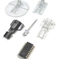
Figure 5. Exploded view drawing.
PCB Assembly Considerations
1. Insert the sensor and all other electrical components
2. Insert the LED into the assembly clip and bend the
3. Insert the LED clip assembly into PCB.
4. Wave solder the entire assembly in a no-wash solder
5. Place the lens onto the base plate.
6. Remove the protective kapton tape from optical
7. Insert PCB assembly over the lens onto the base plate
5
CUSTOMER SUPPLIED BASE PLATE
WITH RECOMMENDED ALIGNMENT
FEATURES PER IGES DRAWING
into PCB.
leads 90 degrees.
process utilizing solder fixture. The solder fixture is
needed to protect the sensor during the solder process.
It also sets the correct sensor-to-PCB distance as the
lead shoulders do not normally rest on the PCB surface.
The fixture should be designed to expose the sensor
leads to solder while shielding the optical aperture
from direct solder contact.
aperture of the sensor. Care must be taken to keep
contaminants from entering the aperture. Recommend
not to place the PCB facing up during the entire mouse
assembly process. Recommend to hold the PCB first
vertically for the kapton removal process.
aligning post to retain PCB assembly. The sensor
aperture ring should self-align to the lens.
ADNS-5200 (LED CLIP)
SENSOR
HLMP-ED80 (LED)
CUSTOMER SUPPLIED PCB
ADNS-5100 (LENS)
Figure 6. Block diagram of ADNS-5030 optical mouse sensor.
8. The optical position reference for the PCB is set by the
9. Install mouse top case. There MUST be a feature in
XY_LED
VDD3
GND
base plate and lens. Note that the PCB motion due to
button presses must be minimized to maintain optical
alignment.
the top case to press down onto the PCB assembly to
ensure all components are interlocked to the correct
vertical height.
ADNS-5030
LED DRIVE
IMAGE ARRAY
OSCILLATOR
DSP
NCS
SCLK
MOSI
MISO
NRESET
Related parts for ADNK-5033-FS27
Image
Part Number
Description
Manufacturer
Datasheet
Request
R

Part Number:
Description:
KIT REFERENCE DESIGN ADNK-5030
Manufacturer:
Avago Technologies US Inc.
Datasheet:

Part Number:
Description:
A2700 Sample Kit
Manufacturer:
Avago Technologies US Inc.
Datasheet:

Part Number:
Description:
OPTOCOUPLER GATE DRV 2A 16-SOIC
Manufacturer:
Avago Technologies US Inc.
Datasheet:
Part Number:
Description:
OPTOCOUPLER 2CH 2.5A 16-SOIC
Manufacturer:
Avago Technologies US Inc.
Datasheet:

Part Number:
Description:
OPTOCOUPLER GATE DRV 0.4A 16SOIC
Manufacturer:
Avago Technologies US Inc.
Datasheet:

Part Number:
Description:
OPTOCOUPLER 2.0A 250KHZ 8-DIP
Manufacturer:
Avago Technologies US Inc.
Datasheet:

Part Number:
Description:
OPTOCOUPLER 2.0A 250KHZ GW 8-SMD
Manufacturer:
Avago Technologies US Inc.
Datasheet:

Part Number:
Description:
OPTOCOUPLER 2CH 15MBD 3.3V 8SOIC
Manufacturer:
Avago Technologies US Inc.
Datasheet:
Part Number:
Description:
OPTOCOUPLER DARL-OUT 8-DIP
Manufacturer:
Avago Technologies US Inc.
Datasheet:
Part Number:
Description:
OPTOCOUPLER IGBT DRIVE 0.4A 8DIP
Manufacturer:
Avago Technologies US Inc.
Datasheet:
Part Number:
Description:
OPTOCOUPLER DARL-OUT 8-DIP
Manufacturer:
Avago Technologies US Inc.
Datasheet:

Part Number:
Description:
OPTOCOUPLER 1CH 1MBS 8-SMD GW
Manufacturer:
Avago Technologies US Inc.
Datasheet:
Part Number:
Description:
OPTOCOUPLER GATE DRIVER 8-DIP
Manufacturer:
Avago Technologies US Inc.
Datasheet:

Part Number:
Description:
OPTOCOUPLER GATE DRIVER 8-SMD
Manufacturer:
Avago Technologies US Inc.
Datasheet:

Part Number:
Description:
OPTOCOUPLER PHOTOTRANS 4-SMD
Manufacturer:
Avago Technologies US Inc.
Datasheet: