CDB5376 Cirrus Logic Inc, CDB5376 Datasheet - Page 25
CDB5376
Manufacturer Part Number
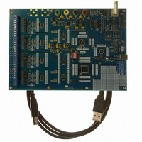
CDB5376
Description
EVALUATION BOARD FOR CS5376
Manufacturer
Cirrus Logic Inc
Datasheets
1.CS5371A-ISZR.pdf
(32 pages)
2.CS4373A-ISZ.pdf
(34 pages)
3.CS5376A-IQZR.pdf
(106 pages)
4.CDB5378.pdf
(16 pages)
5.CDB5376.pdf
(80 pages)
6.CDB5376.pdf
(16 pages)
Specifications of CDB5376
Main Purpose
Seismic Evaluation System
Embedded
Yes, MCU, 8-Bit
Utilized Ic / Part
CS3301A, CS3302A, CS4373A, CS5372A, CS5376A
Primary Attributes
Quad Digital Filter
Secondary Attributes
Graphical User Interface, SPI™ & USB Interfaces
Processor To Be Evaluated
CS330x, CS4373A, CS537x
Interface Type
USB
Lead Free Status / RoHS Status
Contains lead / RoHS non-compliant
Lead Free Status / RoHS Status
Lead free / RoHS Compliant, Contains lead / RoHS non-compliant
Other names
598-1778


7. SYNCHRONIZATION
The CS5376A has a dedicated SYNC input that
aligns the internal digital filter phase and generates
an external signal for synchronizing modulator an-
alog sampling. By providing simultaneous rising
edges to the SYNC pins of multiple CS5376A de-
vices, synchronous sampling across a network can
be guaranteed.
7.1 Pin Description
SYNC - Pin 59
Synchronization input, rising edge triggered.
7.2 MSYNC Generation
The SYNC signal rising edge is used to generate a
retimed synchronization signal, MSYNC. The
MSYNC signal reinitializes internal digital filter
phase and is driven onto the MSYNC output pin to
phase align modulator analog sampling.
The MSEN bit in the digital filter CONFIG register
(0x00) enables MSYNC generation. See “Modula-
tor Interface” on page 39 for more information
about MSYNC.
7.3 Digital Filter Synchronization
The internal MSYNC signal resets the digital filter
state machine to establish a known digital filter
DS612F4
SYNC
MSEN
0
1
Figure 13. Synchronization Block Diagram
Generator
MSYNC
phase. Filter convolutions restart, and the next out-
put word is available one full sample period later.
Repetitive synchronization is supported when
SYNC events occur at exactly the selected output
word rate. In this case, re-synchronization occurs at
the start of a convolution cycle when the digital fil-
ter state machine is already reset.
7.4 Modulator Synchronization
The external MSYNC signal phase aligns modula-
tor analog sampling when connected to the
CS5371A/72A MSYNC input. This ensures syn-
chronous analog sampling relative to MCLK.
Repetitive synchronization of the modulators is
supported when SYNC events occur at exactly the
selected output word rate. In this case, synchroni-
zation will occur at the start of analog sampling.
7.5 Test Bit Stream Synchronization
When the test bit stream generator is enabled, an
MSYNC signal can reset the internal data pointer.
This restarts the test bit stream from the first data
point to establish a known output signal phase.
The TSYNC bit in the digital filter TBSCFG regis-
ter (0x2A) enables synchronization of the test bit
stream by MSYNC. When TSYNC is disabled, the
test bit stream phase is not affected by MSYNC.
Digital
Filter
MSYNC
Output
TSYNC
0
1
Test Bit
CS5376A
Stream
25
Related parts for CDB5376
Image
Part Number
Description
Manufacturer
Datasheet
Request
R

Part Number:
Description:
Development Kit
Manufacturer:
Cirrus Logic Inc
Datasheet:
Part Number:
Description:
Development Kit
Manufacturer:
Cirrus Logic Inc
Datasheet:


Part Number:
Description:
High-efficiency PFC + Fluorescent Lamp Driver Reference Design
Manufacturer:
Cirrus Logic Inc
Datasheet:
Part Number:
Description:
Development Kit
Manufacturer:
Cirrus Logic Inc
Datasheet:
Part Number:
Description:
Development Kit
Manufacturer:
Cirrus Logic Inc
Datasheet:

Part Number:
Description:
Development Kit
Manufacturer:
Cirrus Logic Inc
Datasheet:
Part Number:
Description:
Development Kit
Manufacturer:
Cirrus Logic Inc
Datasheet:
Part Number:
Description:
Development Kit
Manufacturer:
Cirrus Logic Inc
Datasheet:
Part Number:
Description:
Development Kit
Manufacturer:
Cirrus Logic Inc
Datasheet:

Part Number:
Description:
EVALUATION BOARD FOR CS8427
Manufacturer:
Cirrus Logic Inc
Datasheet:

Part Number:
Description:
BOARD EVAL FOR CS8416 RCVR
Manufacturer:
Cirrus Logic Inc
Datasheet:

Part Number:
Description:
EVALUATION BOARD FOR CS8420
Manufacturer:
Cirrus Logic Inc
Datasheet:

Part Number:
Description:
KIT DEVELOPMENT EP9315 ARM9
Manufacturer:
Cirrus Logic Inc
Datasheet:

Part Number:
Description:
KIT DEVELOPMENT EP9302 ARM9
Manufacturer:
Cirrus Logic Inc
Datasheet: