EVAL6207N STMicroelectronics, EVAL6207N Datasheet - Page 13
EVAL6207N
Manufacturer Part Number
EVAL6207N
Description
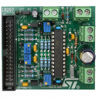
BOARD MOTOR STEPPER/DC L6207 DIP
Manufacturer
STMicroelectronics
Specifications of EVAL6207N
Mfg Application Notes
PractiSPIN AppNote
Design Resources
EVAL6207N Gerber Files EVAL6207N Schematic/Bill of Materials
Main Purpose
Power Management, Motor Control
Embedded
No
Utilized Ic / Part
L6207
Primary Attributes
1 ~ 4 DC Motors or 1 Stepper Motor
Secondary Attributes
Short-Circuit & Thermal Protection
Applications
Motor Control
Processor To Be Evaluated
L6207
Maximum Operating Temperature
+ 125 C
Operating Supply Voltage
5 V
For Use With
497-4138 - EVALUATION BOARD PRACTISPIN
Lead Free Status / RoHS Status
Contains lead / RoHS non-compliant
Other names
497-4934
Available stocks
Company
Part Number
Manufacturer
Quantity
Price


UM0240
4
10-bit digital-to-analog converter (DAC)
The Industrial Communication Board embeds a 10(12)-bit buffered voltage-output DAC
implemented by the AD5317 (AD5327) converter from Analog Devices. The IC provides four
buffered rail-to-rail outputs, in the range 0 ÷ Vcc, with a slew rate of 0.7 V/µs.
The DAC is controlled by the Microcontroller (PC2, PC3, PC4) through a 3-wires serial
interface and is compatible with SPI, QSPI, MICROWIRE and DSP interface standards.
The AD5317 is connected to the microcontroller through its SPI interface (MOSI to DIN and
SCK to SCLK). The references for the four DACs are derived from two reference pins:
VrefAB for VoutA and VoutB, VrefCD for VoutC and VoutD. These reference inputs can be
configured as buffered or unbuffered inputs, through interface command.
On the Industrial board the reference for the output pair AB is connected directly to Vcc
supply, while the VrefCD is available in a double option configuration, thanks to the jumper
JP3:
1.
2.
The AD5317(AD5327) DACs incorporate a power-on reset circuit, which ensures that the
DAC outputs power up to 0 V and remain there until a valid write to the device takes place.
There is also an asynchronous active low CLR pin, connected to the RES line of Industrial
board, that clears all DACs to 0 V. The outputs of all DACs may be updated simultaneously
using the asynchronous LDAC input, controlled by the MCU pin PD1.
The DAC IC contains a power-down feature that reduces the current consumption of the
devices to 300 nA @ 5 V, by setting all outputs in high impedance state. The devices goes
into power-down mode when the pin PD connected to the PD2 MCU line is tied low.
On the PLM connector, the four DAC outputs VOUTA, VOUTB, VOUTC and VOUTD are
available directly, while on the Motor connector, VREF_A and VREF_B are available. These
two signals are provided by the two difference amplifiers U3A and U3B implemented by
LM358.
Connected to the V
Connected to the DAC output VoutB. This option is designed in order to provide a fine
voltage adjustment for the CD output pair DAC reference: this function is suitable, e.g.,
in Motor Control Applications using Micro-stepping technique, for the synthesis of
discrete sinusoidal waveforms. In fact, while the DAC output VoutC or VoutD can
generate a discrete sinusoidal waveform, the DAC output VoutB is able to control the
amplitude of the said signal, in order to control finely the torque of the stepper motor.
CC
supply
10-bit digital-to-analog converter (DAC)
13/39
Related parts for EVAL6207N
Image
Part Number
Description
Manufacturer
Datasheet
Request
R

Part Number:
Description:
STMicroelectronics [RIPPLE-CARRY BINARY COUNTER/DIVIDERS]
Manufacturer:
STMicroelectronics
Datasheet:
Part Number:
Description:
STMicroelectronics [LIQUID-CRYSTAL DISPLAY DRIVERS]
Manufacturer:
STMicroelectronics
Datasheet:

Part Number:
Description:
BOARD EVAL FOR MEMS SENSORS
Manufacturer:
STMicroelectronics
Datasheet:
Part Number:
Description:
NPN TRANSISTOR POWER MODULE
Manufacturer:
STMicroelectronics
Datasheet:
Part Number:
Description:
TURBOSWITCH ULTRA-FAST HIGH VOLTAGE DIODE
Manufacturer:
STMicroelectronics
Datasheet:
Part Number:
Description:
Manufacturer:
STMicroelectronics
Datasheet:
Part Number:
Description:
DIODE / SCR MODULE
Manufacturer:
STMicroelectronics
Datasheet:
Part Number:
Description:
DIODE / SCR MODULE
Manufacturer:
STMicroelectronics
Datasheet:
Part Number:
Description:
Search -----> STE16N100
Manufacturer:
STMicroelectronics
Datasheet:
Part Number:
Description:
Search ---> STE53NA50
Manufacturer:
STMicroelectronics
Datasheet:
Part Number:
Description:
NPN Transistor Power Module
Manufacturer:
STMicroelectronics
Datasheet:
Part Number:
Description:
DIODE / SCR MODULE
Manufacturer:
STMicroelectronics
Datasheet: