EVAL-AD7799EBZ Analog Devices Inc, EVAL-AD7799EBZ Datasheet - Page 24
EVAL-AD7799EBZ
Manufacturer Part Number
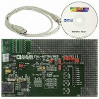
EVAL-AD7799EBZ
Description
BOARD EVALUATION FOR AD7799
Manufacturer
Analog Devices Inc
Specifications of EVAL-AD7799EBZ
Number Of Adc's
1
Number Of Bits
24
Sampling Rate (per Second)
470
Data Interface
Serial
Inputs Per Adc
3 Differential
Input Range
±VREF/gain
Power (typ) @ Conditions
2.5mW @ 470SPS
Voltage Supply Source
Analog and Digital
Operating Temperature
-40°C ~ 105°C
Utilized Ic / Part
AD7799
Lead Free Status / RoHS Status
Lead free / RoHS Compliant


AD7798/AD7799
AV
Along with converting external voltages, the ADC can be used
to monitor the voltage on the AV
equal 1, the voltage on the AV
and the resulting voltage is applied to the ∑-Δ modulator using
an internal 1.17 V reference for analog-to-digital conversion.
This is useful because variations in the power supply voltage
can be monitored.
CALIBRATION
The AD7798/AD7799 provide four calibration modes that can
be programmed via the mode bits in the mode register. These
are internal zero-scale calibration, internal full-scale calibration,
system zero-scale calibration, and system full-scale calibration,
which effectively reduce the offset error and full-scale error to
the order of the noise. After each conversion, the ADC con-
version result is scaled using the ADC calibration registers
before being written to the data register. The offset calibration
coefficient is subtracted from the result prior to multiplication
by the full-scale coefficient.
To start a calibration, write the relevant value to the MD2 to
MD0 bits in the mode register. After the calibration is complete,
the contents of the corresponding calibration registers are
updated, the RDY bit in the status register is set, the DOUT/
RDY pin goes low (if CS is low), and the AD7798/AD7799
revert to idle mode.
During an internal zero-scale or full-scale calibration, the
respective zero-scale and full-scale input are automatically
connected internally to the ADC input pins. A system calibration,
however, expects the system zero-scale and system full-scale
voltages to be applied to the ADC pins before the calibration
mode is initiated. In this way, external ADC errors are removed.
From an operational point of view, a calibration should be
treated like an ADC conversion. A zero-scale calibration (if
required) should always be performed before a full-scale
calibration. System software should monitor the RDY bit in the
status register or the DOUT/ RDY pin to determine the end of
calibration via a polling sequence or an interrupt-driven routine.
DD
MONITOR
DD
pin is internally attenuated by 6,
DD
pin. When Bits CH2 to CH0
Rev. A | Page 24 of 28
Both an internal offset calibration and system offset calibration
take two conversion cycles. An internal offset calibration is not
needed because the ADC itself removes the offset continuously.
To perform an internal full-scale calibration, a full-scale input
voltage is automatically connected to the selected analog input
for this calibration. When the gain equals 1, a calibration takes
two conversion cycles to complete. For higher gains, four
conversion cycles are required to perform the full-scale
calibration. DOUT/ RDY goes high when the calibration is
initiated and returns low when the calibration is complete. The
ADC is placed in idle mode following a calibration. The measured
full-scale coefficient is placed in the full-scale register of the
selected channel. Internal full-scale calibrations cannot be
performed when the gain equals 128. A factory calibration
is performed at this gain setting, and the factory value is
automatically loaded into the full-scale register when the gain is
set to 128. With this gain setting, a system full-scale calibration
can be performed. A full-scale calibration is required each time
the gain of a channel is changed to minimize the full-scale error.
An internal full-scale calibration can only be performed at
specified update rates. For gains of 1, 2, and 4, an internal full-
scale calibration can be performed at any update rate. However,
for higher gains, internal full-scale calibrations must be performed
when the update rate is less than or equal to 16.7 Hz, 33.2 Hz,
or 50 Hz. Because the full-scale error does not vary with the
update rate, a calibration at one update rate is valid for all update
rates (assuming the gain or reference source is not changed).
A system full-scale calibration takes two conversion cycles to
complete, irrespective of the gain setting. A system full-scale
calibration can be performed at all gains and update rates. If
system offset calibrations are performed along with system full-
scale calibrations, the offset calibration should be performed
before the system full-scale calibration is initiated.
Related parts for EVAL-AD7799EBZ
Image
Part Number
Description
Manufacturer
Datasheet
Request
R


Part Number:
Description:
BOARD EVAL FOR SI270X-A
Manufacturer:
Silicon Laboratories Inc
Datasheet:

Part Number:
Description:
BUCK CONV REF DESIGN KIT IP1201
Manufacturer:
International Rectifier
Datasheet:
Part Number:
Description:
BOARD DEMO SYNC DUAL BUCK CNVTER
Manufacturer:
International Rectifier
Datasheet:
Part Number:
Description:
BOARD DEMO SYNC BUCK CONVETER
Manufacturer:
International Rectifier
Datasheet:

Part Number:
Description:
EVALBOARD/EB Omnidirectional microphone - Analog
Manufacturer:
Analog Devices
Datasheet:
Part Number:
Description:
EVALBOARD/EB Omnidirectional microphone - Analog
Manufacturer:
Analog Devices
Datasheet:


Part Number:
Description:
BOARD EVAL LED DRIVER LT3756
Manufacturer:
Linear Technology
Datasheet:

Part Number:
Description:
BOARD EVAL FOR AD7741/7742
Manufacturer:
Analog Devices Inc
Datasheet:

Part Number:
Description:
±1.7g Dual-Axis IMEMS Accelerometer Evaluation Board
Manufacturer:
Analog Devices Inc
Datasheet:

Part Number:
Description:
IC MULTIPLIER ANALOG 8-SOIC T/R
Manufacturer:
Analog Devices Inc
Datasheet:

Part Number:
Description:
IC ANALOG MULTIPLIER 8-DIP
Manufacturer:
Analog Devices Inc
Datasheet:
Part Number:
Description:
IC ANALOG MULTIPLIER 8-SOIC
Manufacturer:
Analog Devices Inc
Datasheet:
Part Number:
Description:
IC ANALOG MULTIPLIER 8-DIP
Manufacturer:
Analog Devices Inc
Datasheet: