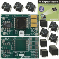
DAK-71A Power Integrations, DAK-71A Datasheet - Page 8

DAK-71A
Manufacturer Part Number
DAK-71A
Description
KIT DESIGN ACCELERATOR DC-DC
Manufacturer
Power Integrations
Series
DPA-Switch®r
Specifications of DAK-71A
Main Purpose
DC/DC, Step Down
Outputs And Type
1, Isolated
Voltage - Output
3.3V
Current - Output
2A
Voltage - Input
36 ~ 72V
Regulator Topology
Flyback
Frequency - Switching
400kHz
Board Type
Bare (Unpopulated) and Fully Populated
Utilized Ic / Part
DPA423, DPA424, DPA425
Lead Free Status / RoHS Status
Not applicable / Not applicable
Power - Output
-
Lead Free Status / Rohs Status
Lead free / RoHS Compliant
Other names
596-1009
Rev. S 12/07
In order to be recognized as a synchronization pulse, the
LINE-SENSE pin needs to stay low (on-time) for at least
120 ns but no more than 2250 ns for 400 kHz (or 3080 ns for
300 kHz) internal switching frequency. In addition, the off-time
must be kept below 7.7 μs, which is a limitation set by the
lowest synchronization frequency of 128 kHz allowed by the
chip. The effective DC
calculated as 0.75
7.7 μs may force the CONTROL pin to go into the hysteretic
mode and initiate a soft-start cycle at next turn-on.
Soft-Start
Two on-chip soft-start functions are activated at start-up with a
duration of 5 ms (typical). Maximum duty cycle starts from 0%
and linearly increases to the default maximum of 75% at the
end of the 5 ms duration and the current limit starts from about
85% and linearly increases to 100% at the end of the
5 ms duration. In addition to start-up, soft-start is also activated
at each restart attempt during auto-restart and when restarting
after being in hysteretic regulation of CONTROL pin voltage (V
due to remote off or thermal shutdown conditions. This
effectively minimizes current and voltage stresses on the output
MOSFET, the clamp circuit and the output rectifi er during start-
up. This feature also helps minimize output overshoot and
prevents saturation of the transformer during start-up.
Shutdown/Auto-Restart
To minimize DPA-Switch power dissipation under fault
conditions, the shutdown/auto-restart circuit turns the power
supply on and off at an auto-restart duty cycle of typically 4% if
an out of regulation condition persists. Loss of regulation
interrupts the external current into the CONTROL pin. V
regulation changes from shunt mode to the hysteretic auto-
restart mode as described in CONTROL pin operation section.
When the fault condition is removed, the power supply output
becomes regulated, V
normal operation of the power supply resumes.
Hysteretic Over-Temperature Protection
Over temperature protection is provided by a precision analog
circuit that turns the output MOSFET off when the junction
temperature exceeds the thermal shutdown temperature
Line-Sense and External Current Limit Pin Table*
Figure Number ➧
*This table is only a partial list of many LINE-SENSE and EXTERNAL CURRENT LIMIT Pin Confi gurations that are possible.
Three Terminal Operation
Undervoltage
Overvoltage
Line Feed-Forward (DC
Overload Power Limiting
External Current Limit
Remote ON/OFF
Synchronization
Table 2.
8
Typical LINE-SENSE and EXTERNAL CURRENT LIMIT Pin Confi gurations.
DPA422-426
×
f
SYNC
C
MAX
MAX
regulation returns to shunt mode, and
/f
for synchronization operation can be
)
OSC
. An off-time longer than
11
✓
12
✓
✓
✓
13
✓
14
✓
C
15
C
✓
),
(137 °C typical). When the junction temperature cools to below
the hysteretic temperature (110 °C typical), normal operation
resumes providing automatic recovery. V
hysteretic mode and a 4.8 V to 5.8 V (typical) sawtooth
waveform is present on the CONTROL pin while in thermal
shutdown.
Bandgap Reference
All critical DPA-Switch internal voltages are derived from a
temperature-compensated bandgap reference. This reference
is also used to generate a temperature-compensated current
reference that is trimmed to accurately set the switching
frequency, current limit, and the line OV/UV thresholds.
DPA-Switch has improved circuitry to maintain all of the above
critical parameters within very tight absolute and temperature
tolerances.
High-Voltage Bias Current Source
This current source biases DPA-Switch from the DRAIN pin and
charges the CONTROL pin external capacitance during start-up
or hysteretic operation. Hysteretic operation occurs during
auto-restart, remote off and over-temperature shutdown. In this
mode of operation, the current source is switched on and off
with an effective duty cycle of approximately 20%. This duty
cycle is determined by the ratio of CONTROL pin charge (I
and discharge currents (I
turned off during normal operation when the output MOSFET is
switching. The effect of the current source switching may be
seen on the DRAIN voltage waveform as small disturbances,
which is normal.
Using Feature Pins
FREQUENCY (F) Pin Operation
The FREQUENCY pin is a digital input pin. Shorting the
FREQUENCY pin to SOURCE pin selects the nominal switching
frequency of 400 kHz (Figure 9) which is suited for most
applications. For other applications that may benefi t from lower
switching frequency, a 300 kHz switching frequency can be
selected by shorting the FREQUENCY pin to the CONTROL pin
(Figure 10). This pin should not be left open.
16
✓
✓
17
✓
18
✓
19
✓
✓
CD1
and I
20
✓
✓
CD2
). This current source is
21
✓
✓
✓
✓
✓
C
is regulated in
22
✓
✓
✓
✓
www.powerint.com
23
✓
✓
✓
✓
C(CH)
24
✓
)


