EVL6566A-75WADP STMicroelectronics, EVL6566A-75WADP Datasheet - Page 29
EVL6566A-75WADP
Manufacturer Part Number
EVL6566A-75WADP
Description
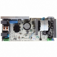
BOARD EVAL FOR L6566A
Manufacturer
STMicroelectronics
Type
Power Factor Correctionr
Datasheets
1.L6566ATR.pdf
(51 pages)
2.TSM1014IDT.pdf
(10 pages)
3.L6563ATR.pdf
(39 pages)
4.EVL6566A-75WADP.pdf
(8 pages)
Specifications of EVL6566A-75WADP
Main Purpose
AC/DC, Primary and Secondary Side with PFC
Outputs And Type
1, Isolated
Power - Output
75W
Voltage - Output
19V
Current - Output
4A
Voltage - Input
90 ~ 264VAC
Frequency - Switching
65kHz
Board Type
Fully Populated
Utilized Ic / Part
L6563, L6566A, TSM1014
Input Voltage
90 V to 264 V
Output Voltage
19 V
Dimensions
78 mm x 174 mm
Product
Power Management Modules
Lead Free Status / RoHS Status
Lead free / RoHS Compliant
Regulator Topology
-
Lead Free Status / Rohs Status
Lead free / RoHS Compliant
For Use With/related Products
L6563, L6566A
Other names
497-6449
Available stocks
Company
Part Number
Manufacturer
Quantity
Price


L6566A
Figure 17. Left: overcurrent setpoint vs VFF voltage; right: line feedforward function block
V
1.2
0.8
0.6
0.4
0.2
csx
1
0
0
[V]
0.5
Experience shows that this value is typically lower than the real one. Once the maximum
peak primary current, I
the value of Rs can be determined from (2):
Equation 7
The converter is then tested on the bench to find the output power level Pout
regulation is lost (because overcurrent is being tripped) both at Vin = Vin
Vin = Vin
If Pout
increasing; if Pout
needs decreasing. This will go on until the difference between the two values is acceptably
low. Once found the true k
from the target; to correct this, the sense resistor Rs needs adjusting and the above tuning
process will be repeated with the new Rs value. Typically a satisfactory setting is achieved in
no more than a couple of iterations.
In applications where this function is not wanted, e.g. because the PFC stage regulates at a
fixed voltage, the VFF pin can be simply grounded, directly or through a resistor, depending
on whether one wants the OVP function to be auto-restart or latched mode (see
“
maximum value of 1 V. If a lower setpoint is desired to reduce the power dissipation on Rs,
the pin can be also biased at a fixed voltage using a divider from VREF (pin 10).
If the FF option is selected the Line Feedforward function can be still used to compensate for
the total propagation delay Td of the current sense chain (internal propagation delay td
plus the turn-off delay of the external MOSFET), which in standard current mode PWM
controllers is done by adding an offset on the current sense pin proportional to the input
voltage. In that case the divider ratio k, which will be much smaller as compared to that used
with the QR option selected, can be calculated with the following equation:
Chapter 5.11: OVP block on page 35
1
lim
1.5
V
max
@ Vin
VFF
.
[V]
V
COMP
2
= Upper clamp
max
lim
2.5
> Pout
@ Vin
PKpmax
3
lim
opt
max
@ Vin
in this way, it is possible that Pout
, occurring at minimum input voltage Vinmin has been found,
3.5
< Pout
min
To PFC's OV
Rs
lim
”). The overcurrent setpoint will be then fixed at the
sensing
the system is still undercompensated and k needs
=
COMP
@ Vin
1
PFC Output Bus
R1B
−
R2
9
I
L6566A
k
PKp
opt
3
min
15
R1A
max
V
VFF
the system is overcompensated and k
in
FORWARD
VOLTAGE
min
FEED
OVP settings
Optional for
Vcsx
1.5 V
CS
7
+
+
+
Hiccup
-
-
-
PWM
OCP
lim
turns out slightly different
Rs
Application information
Clock/ZCD
min
R
S
Q
and
lim
DISABLE
where
DRIVER
4
29/51
(H-L)
GD
Related parts for EVL6566A-75WADP
Image
Part Number
Description
Manufacturer
Datasheet
Request
R

Part Number:
Description:
BOARD DEMO FOR L6563/LL6566A
Manufacturer:
STMicroelectronics
Datasheet:

Part Number:
Description:
STMicroelectronics [RIPPLE-CARRY BINARY COUNTER/DIVIDERS]
Manufacturer:
STMicroelectronics
Datasheet:
Part Number:
Description:
STMicroelectronics [LIQUID-CRYSTAL DISPLAY DRIVERS]
Manufacturer:
STMicroelectronics
Datasheet:

Part Number:
Description:
BOARD EVAL FOR MEMS SENSORS
Manufacturer:
STMicroelectronics
Datasheet:
Part Number:
Description:
NPN TRANSISTOR POWER MODULE
Manufacturer:
STMicroelectronics
Datasheet:
Part Number:
Description:
TURBOSWITCH ULTRA-FAST HIGH VOLTAGE DIODE
Manufacturer:
STMicroelectronics
Datasheet:
Part Number:
Description:
Manufacturer:
STMicroelectronics
Datasheet:
Part Number:
Description:
DIODE / SCR MODULE
Manufacturer:
STMicroelectronics
Datasheet:
Part Number:
Description:
DIODE / SCR MODULE
Manufacturer:
STMicroelectronics
Datasheet:
Part Number:
Description:
Search -----> STE16N100
Manufacturer:
STMicroelectronics
Datasheet:
Part Number:
Description:
Search ---> STE53NA50
Manufacturer:
STMicroelectronics
Datasheet:
Part Number:
Description:
NPN Transistor Power Module
Manufacturer:
STMicroelectronics
Datasheet: