CDB43L21 Cirrus Logic Inc, CDB43L21 Datasheet - Page 5
CDB43L21
Manufacturer Part Number
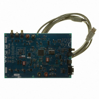
CDB43L21
Description
BOARD EVAL FOR CS43L21 DAC
Manufacturer
Cirrus Logic Inc
Datasheet
1.CDB-43L21.pdf
(25 pages)
Specifications of CDB43L21
Description/function
Audio D/A
Operating Supply Voltage
5 V
Product
Audio Modules
For Use With/related Products
CS43L21
Lead Free Status / RoHS Status
Contains lead / RoHS non-compliant
Lead Free Status / RoHS Status
Lead free / RoHS Compliant, Contains lead / RoHS non-compliant
Other names
598-1528


DS723DB1
1.5
1.6
1.7
1.8
Section 2. “Software Mode Control” on page 7
configuration details.
CS8415 Digital Audio Receiver
A complete description of the CS8415 receiver
interface are included in the CS8415 data sheet.
The CS8415 converts the input S/PDIF data stream from either the optical or the RCA connector into PCM
data for the CS43L21. The CS8415 operates in master or slave mode, generates a 256xFs master clock,
and can operate in either the Left-Justified or I²S interface format.
Selections are made in the control port of the FPGA, accessible through the “General Configurations” tab
of the Cirrus FlexGUI software or through the on-board “FPGA H/W Control” switches.
Mode Control” on page 7
Oscillator
The on-board oscillator provides one of the system master clocks. Selections are made in the control port
of the FPGA, accessible through the “General Configurations” tab of the Cirrus FlexGUI software or through
the on-board switches, “FPGA H/W Control.”
“Hardware Mode Control” on page 11
The oscillator is mounted in pin sockets, allowing easy removal or replacement. Additional sockets are also
installed, allowing the optional use of a half-can- or full-can-sized oscillator.
I/O Stake Headers
The evaluation board has been designed to allow interfacing with external systems via a serial port header
(reference designation J5) and a control port header, “CS43L21 S/W Control.” The serial port header pro-
vides access to the serial audio signals required to interface with a DSP
are made in the control port of the FPGA, accessible through the “General Configurations” tab of the Cirrus
FlexGUI software or through the on-board “FPGA H/W Control” switches.
trol” on page 7
The control port header provides bidirectional access to the SPI™/I²C
ing all the shunt jumpers from the “PC” position. The user may then choose to connect a ribbon cable to the
“CONTROL” position, allowing operation of the CS43L21 in a user-application for system development. A
single “GND” row for the ribbon cable’s ground connection is provided to maintain signal integrity. Two un-
populated pull-up resistors are also available should the user choose to use the CDB for the I²C power rail.
Analog Outputs
RCA connectors are connected directly to the output of the CS43L21 to allow evaluation of the ground-cen-
tered analog outputs. The Right Channel and Left Channel stake headers optionally connect a passive-fil-
tered output to the RCA connectors. For evaluation of the CS43L21’s drive strength into a load, the 16 W
HP Load stake headers connect the analog outputs to 16 W. Headphones may also be connected to the
1/8th inch jack. When connecting headphones, the 16 Ω load resistors should be disconnected by removing
the jumpers on each stake header.
One of the analog outputs may be connected to a speaker driver through the “Speaker” stake header. A
mono speaker may then be driven via the red and black banana jack. The red banana jack designates the
positive terminal and the black designates the negative.
and
Section 3. “Hardware Mode Control” on page 11
and
Section 3. “Hardware Mode Control” on page 11
provide configuration details.
Section 2. “Software Mode Control” on page 7
and
(Figure 12 on page
Section 3. “Hardware Mode Control” on page 11
18) and a discussion of the digital audio
®
provide configuration details.
control port signals by simply remov-
(Figure 13 on page
Section 2. “Software Mode Con-
provide configuration details.
Section 2. “Software
CDB43L21
19). Selections
and
Section 3.
provide
5
Related parts for CDB43L21
Image
Part Number
Description
Manufacturer
Datasheet
Request
R

Part Number:
Description:
EVAL BOARD FOR CS43L21
Manufacturer:
Cirrus Logic Inc
Datasheet:

Part Number:
Description:
Development Kit
Manufacturer:
Cirrus Logic Inc
Datasheet:
Part Number:
Description:
Development Kit
Manufacturer:
Cirrus Logic Inc
Datasheet:


Part Number:
Description:
High-efficiency PFC + Fluorescent Lamp Driver Reference Design
Manufacturer:
Cirrus Logic Inc
Datasheet:
Part Number:
Description:
Development Kit
Manufacturer:
Cirrus Logic Inc
Datasheet:
Part Number:
Description:
Development Kit
Manufacturer:
Cirrus Logic Inc
Datasheet:

Part Number:
Description:
Development Kit
Manufacturer:
Cirrus Logic Inc
Datasheet:
Part Number:
Description:
Development Kit
Manufacturer:
Cirrus Logic Inc
Datasheet:
Part Number:
Description:
Development Kit
Manufacturer:
Cirrus Logic Inc
Datasheet:

Part Number:
Description:
EVALUATION BOARD FOR CS8427
Manufacturer:
Cirrus Logic Inc
Datasheet:

Part Number:
Description:
BOARD EVAL FOR CS8416 RCVR
Manufacturer:
Cirrus Logic Inc
Datasheet:

Part Number:
Description:
EVALUATION BOARD FOR CS8420
Manufacturer:
Cirrus Logic Inc
Datasheet:

Part Number:
Description:
KIT DEVELOPMENT EP9315 ARM9
Manufacturer:
Cirrus Logic Inc
Datasheet:

Part Number:
Description:
KIT DEVELOPMENT EP9302 ARM9
Manufacturer:
Cirrus Logic Inc
Datasheet: