RDK-131 Power Integrations, RDK-131 Datasheet
RDK-131
Specifications of RDK-131


Related parts for RDK-131


RDK-131 Summary of contents
Page 1
... The products and applications illustrated herein (including circuits external to the products and transformer construction) may be covered by one or more U.S. and foreign patents or potentially by pending U.S. and foreign patent applications assigned to Power Integrations. A complete list of Power Integrations’ patents may be found at www.powerint.com. ...
Page 2
... Competitive Product EMI.................................................................................21 11 Revision History......................................................................................................22 Important Note: This board has no safety isolation. Therefore, all testing should be performed using an isolation transformer to provide the AC input to the prototype board. Power Integrations, Inc. Tel: +1 408 414 9200 Fax: +1 408 414 9201 www.powerint.com Page ...
Page 3
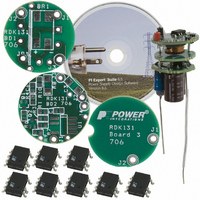
... The report contains the power supply specification, a circuit diagram, a complete bill of materials, the PI Xls spreadsheet results for the design, the printed circuit board layouts, and performance data. Figure 1 – Photographs of (Top and Side views) Populated Circuit Board Assembly. Page Power Integrations Tel: +1 408 414 9200 Fax: +1 408 414 9201 www.powerint.com ...
Page 4
... Figure 2 – Mechanical Positioning of the Power Supply Assembly Inside the GU10 Bulb Socket Base. Power Integrations, Inc. Tel: +1 408 414 9200 Fax: +1 408 414 9201 www.powerint.com Page ...
Page 5
... V OUT1 0.3 I OUT1 3 P OUT η 62 Meets EN55022B/CISPR22B No input to output isolation AMB Tel: +1 408 414 9200 Fax: +1 408 414 9201 Units Comment VAC 2 Wire – Not applicable V o ± 10 Measured W OUT o C Free convection, sea level Power Integrations www.powerint.com ...
Page 6
... Circuit Diagram Figure 3a – Circuit Diagram of Filter Board. Figure 3b – Circuit Diagram of Converter Board. Power Integrations, Inc. Tel: +1 408 414 9200 Fax: +1 408 414 9201 www.powerint.com Page ...
Page 7
... In this design two 250 V rated diodes, D1 and D2, were used for space reasons, however a single 600 V diode could be used (in this case the voltage across C2 would be equal to the output voltage). Page Power Integrations Tel: +1 408 414 9200 Fax: +1 408 414 9201 www.powerint.com ...
Page 8
... However as the FB pin has a voltage of 1.65 V this resulted in unacceptable dissipation (0 1. 0.5 W) inside the GU10 enclosure. However in less thermally challenging designs this approach may be used. Power Integrations, Inc. Tel: +1 408 414 9200 Fax: +1 408 414 9201 www.powerint.com Page ...
Page 9
... Converter Board (Bottom and Top Side) Page Filter Board Figure 4 – Printed Circuit Board Layouts. Tel: +1 408 414 9200 Fax: +1 408 414 9201 Power Integrations www.powerint.com ...
Page 10
... W3 Ft. 0.07 10 SJP1 Ft. 0.15 11 SW1 Ft. 0.06 12 SW2 Ft. Power Integrations, Inc. Tel: +1 408 414 9200 Fax: +1 408 414 9201 www.powerint.com Mfg Part Description Number 600 V, 0.5 A, Bridge MB6S Rectifier, SMD, TO-269AA 4.7 µF, 380 V, Electrolytic, XX380VB4R7M8 (8 x 11.5) X11LL PCB Terminal Hole, 22 ...
Page 11
... Tel: +1 408 414 9200 Fax: +1 408 414 9201 Mfg Comment Panasonic Panasonic Diode Inc. On Semi N/A ICE Components Diodes Inc Diodes Inc Panasonic Panasonic Panasonic Panasonic Panasonic Panasonic Power Integrations Solder wire in J2 Location Alpha (teflon tubing is not required) Keystone Keystone Power Integrations www.powerint.com ...
Page 12
... DIODE VD VRR IF TRR Diode Recommendation OUTPUT INDUCTOR L_TYP L L_R OPERATING MODE KL_TOL K_LOSS ILRMS Power Integrations, Inc. Tel: +1 408 414 9200 Fax: +1 408 414 9201 www.powerint.com Spreadsheet Customer 85 Volts Minimum AC Input Voltage Volts Maximum AC Input Voltage 50 Hertz Line Frequency Volts Output Voltage ...
Page 13
... Feedback Capacitor 39092 uF If the output Voltage is greater than total output and system capacitance is greater than 100 uF, a soft start capacitor between 1uF and recommended. See AN-37 for details Tel: +1 408 414 9200 Fax: +1 408 414 9201 Power Integrations www.powerint.com ...
Page 14
... Table 1: Efficiency data measured at different AC input line voltages. 1 0.9 0.8 0.7 0.6 0.5 0.4 0.3 0.2 70 120 Figure 5 – Efficiency vs. Input Voltage, Room Temperature. Power Integrations, Inc. Tel: +1 408 414 9200 Fax: +1 408 414 9201 www.powerint.com VAC IN Efficiency 85 0.642 115 0.639 220 0.588 265 0.562 ...
Page 15
... Note: When driving a LED load operation at <6V would not occur, therefore current walkout behavior is acceptable. Page 150 200 Input Voltage (VAC) 0.15 0.2 0.25 Output Current (mA) Tel: +1 408 414 9200 Fax: +1 408 414 9201 250 300 85 VAC 265VAC 0.3 0.35 0.4 0.45 Power Integrations www.powerint.com ...
Page 16
... Output Current and Voltage Figure 9 – 85 VAC, Full Load. Upper div. OUT , 100 mA, 20 µs / div. Lower: I OUT Power Integrations, Inc. Tel: +1 408 414 9200 Fax: +1 408 414 9201 www.powerint.com Figure 8 – 265 VAC, Full Load Upper 100 V / div. DRAIN 0. div, 5 µs / div. ...
Page 17
... RDR-131 LED Driver – LNK306DN Figure 12 – 265 VAC, Full Load. Upper 100 V / div. BULK Lower 200 mA div. DRAIN Figure 14 – 265 VAC, Full Load. Upper 200 V / div. BULK Lower 200 mA div. DRAIN Power Integrations Tel: +1 408 414 9200 Fax: +1 408 414 9201 www.powerint.com ...
Page 18
... Fault Conditions Figure 17 – Drain Current with Output Shorted. 500 mA/div div. Vin = 265 VAC Note: Peak drain current is 1.95 Amps. Power Integrations, Inc. Tel: +1 408 414 9200 Fax: +1 408 414 9201 www.powerint.com Figure 16 – 265 VAC Full Load. Upper div. ...
Page 19
... These results indicate that additional heatsinking may be required for example by arranging the LED heatsink to contact the top of the SO-8C package of U1. Page Source Pin Temperature (° 103 Power Integrations Tel: +1 408 414 9200 Fax: +1 408 414 9201 www.powerint.com ...
Page 20
... Power Integrations, Inc. Tel: +1 408 414 9200 Fax: +1 408 414 9201 www.powerint.com 1 MHz LIMIT CHECK MARG LINE EN55022A MARG LINE EN55022Q MARG Figure 19 – Conducted EMI at 230 VAC. 1 MHz LIMIT CHECK MARG LINE EN55022A MARG LINE EN55022Q MARG Figure 20 – Conducted EMI at 115 VAC. ...
Page 21
... Page RBW 9 kHz Marker 1 [ 100 ms 89.31 dBµV Att 10 dB AUTO PREAMP OFF 182.849162999 kHz 1 MHz 10 MHz LIMIT CHECK FAIL LINE EN55022A FAIL LINE EN55022Q FAIL Tel: +1 408 414 9200 Fax: +1 408 414 9201 SGL TDF 30 MHz Power Integrations www.powerint.com ...
Page 22
... Revision History Date Author 02/16/2007 JAJ 03/7/2007 Power Integrations, Inc. Tel: +1 408 414 9200 Fax: +1 408 414 9201 www.powerint.com Revision Description & changes 1.0 Initial publication 1.1 Updated pictures Reviewed Page ...
Page 23
... Page Notes Power Integrations Tel: +1 408 414 9200 Fax: +1 408 414 9201 www.powerint.com ...
Page 24
... For the latest updates, visit our website: www.powerint.com Power Integrations reserves the right to make changes to its products at any time to improve reliability or manufacturability. Power Integrations does not assume any liability arising from the use of any device or circuit described herein. POWER INTEGRATIONS MAKES NO WARRANTY HEREIN AND SPECIFICALLY DISCLAIMS ALL WARRANTIES INCLUDING, WITHOUT LIMITATION, THE IMPLIED WARRANTIES OF MERCHANTABILITY, FITNESS FOR A PARTICULAR PURPOSE, AND NON-INFRINGEMENT OF THIRD PARTY RIGHTS ...