RDK-131 Power Integrations, RDK-131 Datasheet - Page 8
RDK-131
Manufacturer Part Number
RDK-131
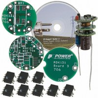
Description
KIT REF DESIGN LED LINKSWITCH TN
Manufacturer
Power Integrations
Series
LinkSwitch-TNr
Specifications of RDK-131
Current - Output / Channel
300mA
Outputs And Type
1, Non-Isolated
Voltage - Output
10V
Features
fits within GU10 lamp base
Voltage - Input
85 ~ 265VAC
Utilized Ic / Part
LNK306DN
Lead Free Status / RoHS Status
Not applicable / Not applicable
Other names
596-1127


This voltage is divided by R7 and R1 so the voltage at the FB pin is 1.65 V when the
output voltage reaches ~12 V. Due to the interaction with the current sense circuit and
the small output capacitor value the actual peak no-load voltage is limited to ~18 V.
Current feedback is provided by sensing the voltage drop across R8 and R10, which is
filtered by R4 and C6. Once the voltage drop exceeds the VBE of Q1, both Q1 and Q2
turn on, feeding additional current into the FB pin of U1 from C2. By adjusting the ratio
of enabled to disabled cycles the average output current is controlled. As the VBE of
Q1 varies with temperature the circuit exhibits a negative output current temperature
coefficient.
Resistor R11 provides a minimum load to ensure correct operation at zero load.
This relatively complicated current sense can be simplified by using the FB pin directly
to sense the voltage drop across the sense resistors. However as the FB pin has a
voltage of 1.65 V this resulted in unacceptable dissipation (0.3 A x 1.65 V = 0.5 W)
inside the GU10 enclosure. However in less thermally challenging designs this
approach may be used.
Power Integrations, Inc.
Tel: +1 408 414 9200 Fax: +1 408 414 9201
www.powerint.com
Page 8 of 24
Related parts for RDK-131
Image
Part Number
Description
Manufacturer
Datasheet
Request
R

Part Number:
Description:
KIT REF DESIGN FOR LNK457D
Manufacturer:
Power Integrations
Datasheet:

Part Number:
Description:
REFERENCE DESIGN LINKSWITCH-PH
Manufacturer:
Power Integrations
Datasheet:

Part Number:
Description:
KIT REF DESIGN FOR LNK403EG
Manufacturer:
Power Integrations
Datasheet:

Part Number:
Description:
KIT REF DESIGN FOR LNK406EG
Manufacturer:
Power Integrations
Datasheet:

Part Number:
Description:
KIT REF DESIGN LINKSWITCH-CV
Manufacturer:
Power Integrations
Datasheet:

Part Number:
Description:
KIT REF DESIGN LINKSWITCH 2
Manufacturer:
Power Integrations
Datasheet:

Part Number:
Description:
Specifications: Family: Eval Boards - DC/DC & AC/DC (Off-Line) SMPS ; Series: HiperLCS™ ; Main Purpose: DC/DC, Step Down ; Outputs and Type: 1, Isolated ; Power - Output: 150W ; Voltage - Output: 24V ; Current - Output: 6.25A ; Voltage - Input:
Manufacturer:
Power Integrations, Inc.
Datasheet:

Part Number:
Description:
KIT DESIGN REF TINYSWITCH-III
Manufacturer:
Power Integrations
Datasheet:

Part Number:
Description:
KIT DESIGN REF LINKSWITCH LP
Manufacturer:
Power Integrations
Datasheet:
Part Number:
Description:
KIT REF DESIGN PG LINKSWITCH-II
Manufacturer:
Power Integrations
Datasheet:
Part Number:
Description:
REFERENCE DESIGN LINKSWITCH-PL
Manufacturer:
Power Integrations
Datasheet:
Part Number:
Description:
REFERENCE DESIGN LINKSWITCH-PH
Manufacturer:
Power Integrations
Datasheet:

Part Number:
Description:
KIT REF DESIGN 36-72W MOTOR DRVR
Manufacturer:
Power Integrations
Datasheet:
Part Number:
Description:
Specifications: Manufacturer: Power Integrations ; Output Voltage: 380 VDC ; Input / Supply Voltage (Max): 264 VAC ; Input / Supply Voltage (Min): 90 VAC ; Mounting Style: Through Hole ; Output Current: 0.913 A ; Output Power: 347 W
Manufacturer:
Power Integrations, Inc.

Part Number:
Description:
KIT REF DESIGN TOP HX FOR TOP258
Manufacturer:
Power Integrations
Datasheet: