EVL130W-STRLIG STMicroelectronics, EVL130W-STRLIG Datasheet
EVL130W-STRLIG
Specifications of EVL130W-STRLIG
Available stocks


Related parts for EVL130W-STRLIG


EVL130W-STRLIG Summary of contents
Page 1
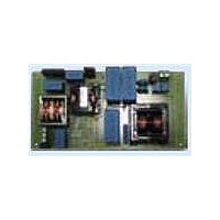
... LED. This application note describes the characteristics and features of a 130 W demonstration board (EVL130W-STRLIG), tailored to an LED power supply specification for street lighting. The circuit is composed of two stages: a front-end PFC using the L6562AT and an LLC resonant converter based on the L6599AT. ...
Page 2
Contents Contents 1 Main characteristics and circuit description . . . . . . . . . . . . . . . . . . . . . 6 1.1 Power Factor corrector . . . . . . ...
Page 3
... EVL130W-STRLIG demonstration board: overall efficiency vs. load . . . . . . . . . . . . . . . . . 10 Table 2. Thermal maps reference points - PCB top side . . . . . . . . . . . . . . . . . . . . . . . . . . . . . . . . . 21 Table 3. Thermal maps reference points - PCB bottom side . . . . . . . . . . . . . . . . . . . . . . . . . . . . . . 22 Table 4. EVL130W-STRLIG demonstration board: bill of material . . . . . . . . . . . . . . . . . . . . . . . . . . 25 Table 5. PFC coil winding data . . . . . . . . . . . . . . . . . . . . . . . . . . . . . . . . . . . . . . . . . . . . . . . . . . . . . 30 Table 6. Transformer winding data . . . . . . . . . . . . . . . . . . . . . . . . . . . . . . . . . . . . . . . . . . . . . . . . . . 32 Table 7. Document revision history . . . . . . . . . . . . . . . . . . . . . . . . . . . . . . . . . . . . . . . . . . . . . . . . . 34 ...
Page 4
... List of figures List of figures Figure 1. EVL130W-STRLIG: 130 W SMPS for LED street lighting applications . . . . . . . . . . . . . . . . 1 Figure 2. EVL130W-STRLIG demonstration board: electrical diagram . . . . . . . . . . . . . . . . . . . . . . . . 9 Figure 3. EVL130W-STRLIG demonstration board: efficiency vs. load . . . . . . . . . . . . . . . . . . . . . . . 10 Figure 4. EVL130W-STRLIG demonstration board: full-load efficiency vs. VAC . . . . . . . . . . . . . . . . 10 Figure 5. EVL130W-STRLIG demonstration board: compliance to EN61000-3-2 Class-C standard . . . . . . . . . . . . . . . . . . . . . . . . . . . . . . . . . . . . . . . . . . . . . . . . . . . . . . . . . . . . . . . 11 Figure 6. ...
Page 5
AN3106 Figure 32. Thermal map at 230 VAC - full load - PCB top side . . . . . . . . . . . . . . . . . . . . . . ...
Page 6
Main characteristics and circuit description 1 Main characteristics and circuit description The main features of the SMPS are listed here below: Extended input mains range: 85 ÷ 305 V ● ● Output voltage 2.7 A ● Long-life, ...
Page 7
AN3106 1.2 Resonant power stage The downstream converter is a resonant LLC half-bridge stage working with 50 percent fixed duty cycle and variable frequency. It implements the ST L6599AT, integrating all functions necessary to properly control the resonant topology. The ...
Page 8
Main characteristics and circuit description All demonstration boards implement the voltage loop circuitry previously described but in case a current loop is also required, it can be achieved by implementing the following modifications: Replace R30 and R31 0R0 Ω resistors ...
Page 9
... AN3106 Figure 2. EVL130W-STRLIG demonstration board: electrical diagram Main characteristics and circuit description Doc ID 16775 Rev 1 9/35 ...
Page 10
... AC supplies. The efficiency has been measured at 25%, 50%, 75% and 100%, and the average efficiency according to the ES-2 standard has been calculated. As shown in high at both nominal mains. Table 1. EVL130W-STRLIG demonstration board: overall efficiency vs. load 230 Load V [V] I [A] P ...
Page 11
... The measurements are shown in Figure 5 and Figure EVL130W-STRLIG demonstration Figure 5. board: compliance to EN61000-3-2 Class-C standard V = 230 Hz 138 THD = 8.70 0.976 Input current harmonics measurement 6. Figure 100 THD = 3.31 0.994 Doc ID 16775 Rev 1 EVL130W-STRLIG demonstration board: compliance to JEITA-MITI Class-C standard - 50 Hz 141 11/35 ...
Page 12
... 130 W load CH1: AC input mains voltage CH4: AC input mains current give the input current and voltage at nominal input voltage mains Figure 10. EVL130W-STRLIG demonstration board: input current waveform at 100 load CH1: AC input mains voltage CH4: AC input mains current ...
Page 13
... Power Factor vs. output power Input current harmonics measurement Figure 12. EVL130W-STRLIG demonstration board: compliance to JEITA-MITI Class-C standard V = 100 Hz THD = 6.65 0.92 Figure 13 Figure 14. EVL130W-STRLIG demonstration board: Total Harmonic Distortion vs. output power Doc ID 16775 Rev 1 Figure 11 and Figure 12 and Figure 14. As visible, 13/35 ...
Page 14
... PFC CH2: MULT OUT CH3: CS 14/35 Figure 17 some waveforms relevant to the PFC stage have been captured and 115 V AC Figure 16. EVL130W-STRLIG demonstration CH1: V OUT CH3: CS Doc ID 16775 Rev both figures it is visible that the AC Figure 16 board: PFC stage and L6562AT waveforms at 230 full ...
Page 15
... This demonstrates that during the half cycle the circuit is working below the resonant frequency, while during the following half cycle it is working at the resonant frequency. Figure 18. EVL130W-STRLIG demonstration board: PFC stage and L6562AT waveforms at 115 full ...
Page 16
... This de-rating with respect to the rectifiers V RRM Figure 20. EVL130W-STRLIG demonstration board: secondary side LLC waveforms at 230 full load CH1: V_D12 CH3: V OUT Figure 22. EVL130W-STRLIG demonstration board: low frequency ripple on output voltage at 115 full load CH3: V OUT Doc ID 16775 Rev 1 AN3106 RRM ...
Page 17
... The long connection wiring between the power supply and the converters can act as an antenna radiating EMI. Thus local filtering minimizes the radiated EMI. Figure 23 and Figure 24 Figure 24. EVL130W-STRLIG demonstration CH1: PWM dimming signal OUT CH4: SMPS output current Doc ID 16775 Rev 1 ...
Page 18
Functional check The capacitance to be added to the 48 V bus for correct operation with LEDs is around 40 µF. In order to not affect the board MTBF, we suggest using the same type of capacitors already used on ...
Page 19
... The V coil charge pump, and then once the L6599AT starts operating, the V the LLC transformer auxiliary winding. The details of converter sequencing can be found in Figure 28 and Figure Figure 26. EVL130W-STRLIG demonstration AC CH1: Q1_Drain CH3: V OUT . Once V ...
Page 20
... LEDs flashing. As already explained in capacitance on the +48 V. 20/35 Figure 28. EVL130W-STRLIG demonstration - CH1: Q2_Drain CH3: L6599AT V Figure 30. EVL130W-STRLIG demonstration - CH1: Q2_Drain CH3: L6599AT V 30 show a correct startup of the board using an active load, with only the Section 4.3, the board needs an additional 40 µF ...
Page 21
AN3106 5 Thermal map In order to check the design reliability, a thermal mapping by means camera was done. Here below the thermal measures of the board, component side, at nominal input voltage are shown. Some pointers ...
Page 22
Thermal map Figure 33. Thermal map at 115 V Figure 34. Thermal map at 230 V Table 3. Thermal maps reference points - PCB bottom side Point 22/ full ...
Page 23
AN3106 6 Conducted emission precompliance measurement Figure 35 to Figure 38 and nominal mains voltages for both wires, line and neutral. The limits on the diagrams are the EN55022 Class-B norms. As visible on the diagrams, in all test conditions ...
Page 24
Conducted emission precompliance measurement Figure 37. CE average measurement at 230 V Figure 38. CE average measurement at 230 V 24/35 and full load - phase wire AC and full load - neutral wire AC Doc ID 16775 Rev 1 ...
Page 25
... AN3106 7 Bill of material Table 4. EVL130W-STRLIG demonstration board: bill of material Part type / part Case style Des. value / package 4.5 x 12 p.10 mm C10 1 µF 1206 C11 470 nF 0805 C12 2.2 µF 0805 C13 10 µF 1210 C15 4.7 nF 0805 C16 220 pF 0805 7.8 x 7.8 p. ...
Page 26
... Bill of material Table 4. EVL130W-STRLIG demonstration board: bill of material (continued) Part type / part Case style Des. value / package C39 470 nF 0805 9 × 18.0 C4 470 nF p.15 mm C40 10 µF 2220 C41 N. M. 0805 14 × 31 µ × 31 µ × 31 µF p. 27.5mm 4 2 p.10 mm ...
Page 27
... AN3106 Table 4. EVL130W-STRLIG demonstration board: bill of material (continued) Part type / part Case style Des. value / package D6 LL4148 SOD-80 D7 BZV55-B15 SOD-80 D8 LL4148 SOD-80 D9 LL4148 SOD-80 8 FUSE T4A p. 5.08 mm HS1 Heatsink DWG J1 MKDS 1,5 / 3-5,08 p. 5.08 mm PCB term. block, screw conn., pitch MKDS 1,5 / 2-5,08 p. 5.08 mm PCB term. block, screw conn., pitch ...
Page 28
... Bill of material Table 4. EVL130W-STRLIG demonstration board: bill of material (continued) Part type / part Case style Des. value / package R22 39 KΩ 0805 100 Ω R23 0805 R24 1.4 MΩ 1206 R25 82 KΩ 0805 R26 15 KΩ 0805 470 Ω R27 0805 R29 N ...
Page 29
... AN3106 Table 4. EVL130W-STRLIG demonstration board: bill of material (continued) Part type / part Case style Des. value / package 100 Ω R57 0805 R58 150 KΩ 0805 1.5 Ω R59 1206 R6 1.0 MΩ 1206 R60 8.2 KΩ 0805 R61 N. M. 1206 R62 100 KΩ ...
Page 30
PFC coil specifications 8 PFC coil specifications General description and characteristics ● Application type: consumer, home appliance ● Transformer type: open ● Coil former: vertical type pins ● Max. temp. rise: 45 °C ● Max. operating ambient ...
Page 31
AN3106 Mechanical aspect and pin numbering ● Maximum height from PCB ● Coil former type: vertical pins (pins # 10, 12 are removed) ● Pin distance: 3.81 mm ● Row distance: ...
Page 32
Transformer specifications 9 Transformer specifications General description and characteristics ● Application type: consumer, home appliance ● Transformer type: open ● Coil former: horizontal type pins, two slots ● Max. temp. rise: 45 °C ● Max. operating ambient ...
Page 33
AN3106 Mechanical aspect and pin numbering ● Maximum height from PCB ● Coil former type: horizontal pins (pins #1, #3 and #5 removed for PCB reference) ● Pin distance: 5.08 mm ● Row distance: 25.4 ...
Page 34
Revision history 10 Revision history Table 7. Document revision history Date 01-Sep-2010 34/35 Revision 1 Initial release. Doc ID 16775 Rev 1 AN3106 Changes ...
Page 35
... AN3106 Information in this document is provided solely in connection with ST products. STMicroelectronics NV and its subsidiaries (“ST”) reserve the right to make changes, corrections, modifications or improvements, to this document, and the products and services described herein at any time, without notice. All ST products are sold pursuant to ST’s terms and conditions of sale. ...