EVL130W-STRLIG STMicroelectronics, EVL130W-STRLIG Datasheet - Page 15
EVL130W-STRLIG
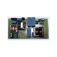
Manufacturer Part Number
EVL130W-STRLIG
Description
BOARD EVAL L6562AT L6599AT
Manufacturer
STMicroelectronics
Specifications of EVL130W-STRLIG
Current - Output / Channel
2.7A
Outputs And Type
1, Isolated
Voltage - Output
48V
Features
EN55022 class B compliant
Voltage - Input
85 ~ 305 V
Utilized Ic / Part
L6562AT, L6599AT
Description/function
SMPS for LED Street Lighting Applications
Data Bus Width
4 bit
Maximum Clock Frequency
30 MHz
Maximum Power Dissipation
130 W
Operating Supply Voltage
85 V to 305 V
Operating Voltage
48 V
Product
Display Modules
Lead Free Status / RoHS Status
Lead free / RoHS Compliant
For Use With/related Products
L6562AT, L6599AT
Other names
497-10541
Available stocks
Company
Part Number
Manufacturer
Quantity
Price


AN3106
4.2
Figure 17. EVL130W-STRLIG demonstration
CH1: V
CH3: CS
OUT
PFC
Half-bridge resonant LLC circuit
The following figures show waveforms relevant to the resonant stage during steady-state
operation. The resonant stage switching frequency is about 100 kHz, in order to have
a good trade-off between transformer losses and dimensions.
The LLC converter has been designed to operate at nominal voltage and full load at the
resonance frequency, but due to the PFC output voltage ripple at twice the mains frequency,
it is driven slightly above and below the resonant tank frequency, according to the
instantaneous value of the PFC output voltage.
In
note that both MOSFETs are turned on when resonant current is flowing through their body
diodes and drain-source voltage is almost zero, thus achieving good efficiency because the
turn-on losses are negligible. The HB MOSFET voltage de-rating and low operating
temperature allow increasing the board’s MTBF.
The current flowing in the resonant tank is sinusoidal. In
asymmetry of operating modes by each half portion of the sine wave. The half cycle is
working at resonant frequency while the other one is working above the resonant frequency.
This is due to a small difference between each half-secondary leakage inductance of the
transformer reflected to the primary side, providing the two slightly different resonant
frequencies. This phenomenon is typically due to a different coupling of the transformer
secondary windings and, in this case, it is not an issue. The slight asymmetry is also visible
in
indicates that for a short time the rectifiers are not conducting. This demonstrates that
during the half cycle the circuit is working below the resonant frequency, while during the
following half cycle it is working at the resonant frequency.
board: PFC stage and L6562AT
waveforms at 115 V - 60 Hz - full
load
Figure 20
Figure 19
CH2: MULT
where the small ringing appearing on both secondary rectifiers anode voltage
some waveforms relevant to the resonant stage ZVS operation are shown. We
Doc ID 16775 Rev 1
Figure 18. EVL130W-STRLIG demonstration
CH1: V
CH3: CS
OUT
PFC
board: PFC stage and L6562AT
waveforms at 115 V - 60 Hz - full
load - detail
Figure 19
CH2: MULT
CH4: Vdrain_Q2
we note a slight
Functional check
15/35
Related parts for EVL130W-STRLIG
Image
Part Number
Description
Manufacturer
Datasheet
Request
R

Part Number:
Description:
BOARD EVAL L6562AT L6599AT
Manufacturer:
STMicroelectronics
Datasheet:
Part Number:
Description:
STMicroelectronics [RIPPLE-CARRY BINARY COUNTER/DIVIDERS]
Manufacturer:
STMicroelectronics
Datasheet:
Part Number:
Description:
STMicroelectronics [LIQUID-CRYSTAL DISPLAY DRIVERS]
Manufacturer:
STMicroelectronics
Datasheet:

Part Number:
Description:
BOARD EVAL FOR MEMS SENSORS
Manufacturer:
STMicroelectronics
Datasheet:
Part Number:
Description:
NPN TRANSISTOR POWER MODULE
Manufacturer:
STMicroelectronics
Datasheet:
Part Number:
Description:
TURBOSWITCH ULTRA-FAST HIGH VOLTAGE DIODE
Manufacturer:
STMicroelectronics
Datasheet:
Part Number:
Description:
Manufacturer:
STMicroelectronics
Datasheet:
Part Number:
Description:
DIODE / SCR MODULE
Manufacturer:
STMicroelectronics
Datasheet:
Part Number:
Description:
DIODE / SCR MODULE
Manufacturer:
STMicroelectronics
Datasheet:
Part Number:
Description:
Search -----> STE16N100
Manufacturer:
STMicroelectronics
Datasheet:
Part Number:
Description:
Search ---> STE53NA50
Manufacturer:
STMicroelectronics
Datasheet:
Part Number:
Description:
NPN Transistor Power Module
Manufacturer:
STMicroelectronics
Datasheet: