LM3429BSTEVAL/NOPB National Semiconductor, LM3429BSTEVAL/NOPB Datasheet - Page 19
LM3429BSTEVAL/NOPB
Manufacturer Part Number
LM3429BSTEVAL/NOPB
Description
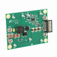
BOARD EVAL FOR BOOST LM3429
Manufacturer
National Semiconductor
Series
PowerWise®r
Specifications of LM3429BSTEVAL/NOPB
Current - Output / Channel
1A
Outputs And Type
1, Non-Isolated
Features
Dimmable
Voltage - Input
10 ~ 26 V
Utilized Ic / Part
LM3429
Core Chip
LM3429
Topology
Buck-Boost
No. Of Outputs
1
Dimming Control Type
PWM / Analog
Development Tool Type
Hardware - Eval/Demo Board
Mcu Supported Families
LM3429 Family
Msl
MSL 1 - Unlimited
Lead Free Status / RoHS Status
Lead free by exemption / RoHS compliant by exemption
Voltage - Output
-
Other names
*LM3429BSTEVAL
*LM3429BSTEVAL/NOPB
LM3429BSTEVAL
*LM3429BSTEVAL/NOPB
LM3429BSTEVAL
Available stocks
Company
Part Number
Manufacturer
Quantity
Price
Company:

Part Number:
LM3429BSTEVAL/NOPB
Manufacturer:
National Semiconductor
Quantity:
135


5. LED RIPPLE CURRENT
Set the nominal LED ripple current (Δi
the output capacitance (C
Buck
Boost and Buck-boost
To set the worst case LED ripple current, use D
solving for C
The minimum allowable RMS output capacitor current rating
(I
Buck
Boost and Buck-boost
6. PEAK CURRENT LIMIT
Set the peak current limit (I
path sense resistor (R
7. LOOP COMPENSATION
Using a simple first order peak current mode control model,
neglecting any output capacitor ESR dynamics, the neces-
sary loop compensation can be determined.
First, the uncompensated loop gain (T
be approximated:
Buck
Boost and Buck-boost
CO-RMS
) can be approximated:
O
.
LIM
):
O
):
LIM
) by solving for the transistor
U
LED-PP
) of the regulator can
), by solving for
MAX
when
19
Where the pole (ω
Buck
Boost
Buck-boost
And the RHP zero (ω
Boost
Buck-boost
And the uncompensated DC loop gain (T
Buck
Boost
Buck-boost
For all topologies, the primary method of compensation is to
place a low frequency dominant pole (ω
that there is ample phase margin at the crossover frequency.
This is accomplished by placing a capacitor (C
COMP pin to GND, which is calculated according to the lower
value of the pole and the RHP zero of the system (shown as
a minimizing function):
If analog dimming is used, C
larger to maintain stability as the LEDs are dimmed to zero.
P1
) is approximated:
Z1
) is approximated:
CMP
should be approximately 4x
P2
U0
) which will ensure
) is approximated:
CMP
www.national.com
) from the
Related parts for LM3429BSTEVAL/NOPB
Image
Part Number
Description
Manufacturer
Datasheet
Request
R

Part Number:
Description:
National Semiconductor [8-Bit D/A Converter]
Manufacturer:
National Semiconductor
Datasheet:
Part Number:
Description:
National Semiconductor [Media Coprocessor]
Manufacturer:
National Semiconductor
Datasheet:
Part Number:
Description:
Digitally Controlled Tone and Volume Circuit with Stereo Audio Power Amplifier, Microphone Preamp Stage and National 3D Sound
Manufacturer:
National Semiconductor
Datasheet:
Part Number:
Description:
Digitally Controlled Tone and Volume Circuit with Stereo Audio Power Amplifier, Microphone Preamp Stage and National 3D Sound
Manufacturer:
National Semiconductor
Datasheet:
Part Number:
Description:
AC97 Rev 2 Codec with Sample Rate Conversion and National 3D Sound
Manufacturer:
National Semiconductor
Part Number:
Description:
Manufacturer:
National Semiconductor
Datasheet:
Part Number:
Description:
Manufacturer:
National Semiconductor
Datasheet:
Part Number:
Description:
General Purpose, Low Voltage, Low Power, Rail-to-Rail Output Operational Amplifiers
Manufacturer:
National Semiconductor
Datasheet:
Part Number:
Description:
8-bit 20 MSPS flash A/D converter.
Manufacturer:
National Semiconductor
Datasheet:
Part Number:
Description:
Low Noise Quad Operational Amplifier
Manufacturer:
National Semiconductor
Datasheet:
Part Number:
Description:
Quad Differential Line Receivers
Manufacturer:
National Semiconductor
Datasheet:
Part Number:
Description:
Quad High Speed Trapezoidal? Bus Transceiver
Manufacturer:
National Semiconductor
Datasheet:
Part Number:
Description:
Dual Line Receiver
Manufacturer:
National Semiconductor
Datasheet:
Part Number:
Description:
TTL to 10k ECL Level Translator with Latch
Manufacturer:
National Semiconductor
Datasheet: