LM3429BSTEVAL/NOPB National Semiconductor, LM3429BSTEVAL/NOPB Datasheet - Page 21
LM3429BSTEVAL/NOPB
Manufacturer Part Number
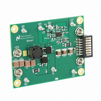
LM3429BSTEVAL/NOPB
Description
BOARD EVAL FOR BOOST LM3429
Manufacturer
National Semiconductor
Series
PowerWise®r
Specifications of LM3429BSTEVAL/NOPB
Current - Output / Channel
1A
Outputs And Type
1, Non-Isolated
Features
Dimmable
Voltage - Input
10 ~ 26 V
Utilized Ic / Part
LM3429
Core Chip
LM3429
Topology
Buck-Boost
No. Of Outputs
1
Dimming Control Type
PWM / Analog
Development Tool Type
Hardware - Eval/Demo Board
Mcu Supported Families
LM3429 Family
Msl
MSL 1 - Unlimited
Lead Free Status / RoHS Status
Lead free by exemption / RoHS compliant by exemption
Voltage - Output
-
Other names
*LM3429BSTEVAL
*LM3429BSTEVAL/NOPB
LM3429BSTEVAL
*LM3429BSTEVAL/NOPB
LM3429BSTEVAL
Available stocks
Company
Part Number
Manufacturer
Quantity
Price
Company:

Part Number:
LM3429BSTEVAL/NOPB
Manufacturer:
National Semiconductor
Quantity:
135


The current rating should be at least 10% higher than the
maximum average diode current (I
Buck
Boost and Buck-boost
Replace D
average diode current (I
(V
11. OUTPUT OVLO
For boost and buck-boost regulators, output OVLO is pro-
grammed with the turn-off threshold voltage (V
the desired hysteresis (V
To set V
Boost
Buck-boost
A small filter capacitor (C
the OVP pin to ground to reduce coupled switching noise.
FD
), solve for the nominal power dissipation (P
TURN-OFF
MAX
with D in the I
, solve for R
D
). Given a diode with forward voltage
HYSO
OVP
OV1
= 47 pF) should be added from
D-MAX
). To set V
:
D-MAX
equation to solve for the
):
HYSO
, solve for R
TURN-OFF
D
):
) and
OV2
:
21
12. INPUT UVLO
For all topologies, input UVLO is programmed with the turn-
on threshold voltage (V
(V
Method #1: If no PWM dimming is required, a two resistor
network can be used. To set V
To set V
Method #2: If PWM dimming is required, a three resistor net-
work is suggested. To set V
and solve for R
R
13. PWM DIMMING METHOD
PWM dimming can be performed several ways:
Method #1: Connect the dimming MosFET (Q
to the nDIM pin and the source to GND. Apply an external
PWM signal to the gate of Q
necessary to properly turn off Q
Method #2: Connect the anode of a Schottky diode to the
nDIM pin. Apply an external inverted PWM signal to the cath-
ode of the same diode.
14. ANALOG DIMMING METHOD
Analog dimming can be performed several ways:
Method #1: Place a potentiometer in series with the R
resistor to dim the LED current from the nominal I
zero.
Method #2: Connect a controlled current source as detailed
in the Analog Dimming section to the CSH pin. Increasing the
current sourced into the CSH node will decrease the LEDs
from the nominal I
UVH
HYS
:
).
TURN-ON
UV1
, solve for R
LED
as in Method #1. To set V
to zero current.
TURN-ON
UV1
DIM
TURN-ON
HYS
:
. A pull down resistor may be
) and the desired hysteresis
3
.
, solve for R
, assume R
3
UV2
) with the drain
HYS
UV2
www.national.com
:
LED
, solve for
= 10 kΩ
to near
CSH
Related parts for LM3429BSTEVAL/NOPB
Image
Part Number
Description
Manufacturer
Datasheet
Request
R

Part Number:
Description:
National Semiconductor [8-Bit D/A Converter]
Manufacturer:
National Semiconductor
Datasheet:
Part Number:
Description:
National Semiconductor [Media Coprocessor]
Manufacturer:
National Semiconductor
Datasheet:
Part Number:
Description:
Digitally Controlled Tone and Volume Circuit with Stereo Audio Power Amplifier, Microphone Preamp Stage and National 3D Sound
Manufacturer:
National Semiconductor
Datasheet:
Part Number:
Description:
Digitally Controlled Tone and Volume Circuit with Stereo Audio Power Amplifier, Microphone Preamp Stage and National 3D Sound
Manufacturer:
National Semiconductor
Datasheet:
Part Number:
Description:
AC97 Rev 2 Codec with Sample Rate Conversion and National 3D Sound
Manufacturer:
National Semiconductor
Part Number:
Description:
Manufacturer:
National Semiconductor
Datasheet:
Part Number:
Description:
Manufacturer:
National Semiconductor
Datasheet:
Part Number:
Description:
General Purpose, Low Voltage, Low Power, Rail-to-Rail Output Operational Amplifiers
Manufacturer:
National Semiconductor
Datasheet:
Part Number:
Description:
8-bit 20 MSPS flash A/D converter.
Manufacturer:
National Semiconductor
Datasheet:
Part Number:
Description:
Low Noise Quad Operational Amplifier
Manufacturer:
National Semiconductor
Datasheet:
Part Number:
Description:
Quad Differential Line Receivers
Manufacturer:
National Semiconductor
Datasheet:
Part Number:
Description:
Quad High Speed Trapezoidal? Bus Transceiver
Manufacturer:
National Semiconductor
Datasheet:
Part Number:
Description:
Dual Line Receiver
Manufacturer:
National Semiconductor
Datasheet:
Part Number:
Description:
TTL to 10k ECL Level Translator with Latch
Manufacturer:
National Semiconductor
Datasheet: