LM3429BSTEVAL/NOPB National Semiconductor, LM3429BSTEVAL/NOPB Datasheet - Page 8
LM3429BSTEVAL/NOPB
Manufacturer Part Number
LM3429BSTEVAL/NOPB
Description
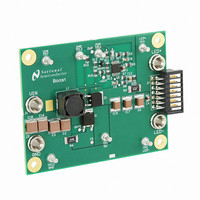
BOARD EVAL FOR BOOST LM3429
Manufacturer
National Semiconductor
Series
PowerWise®r
Specifications of LM3429BSTEVAL/NOPB
Current - Output / Channel
1A
Outputs And Type
1, Non-Isolated
Features
Dimmable
Voltage - Input
10 ~ 26 V
Utilized Ic / Part
LM3429
Core Chip
LM3429
Topology
Buck-Boost
No. Of Outputs
1
Dimming Control Type
PWM / Analog
Development Tool Type
Hardware - Eval/Demo Board
Mcu Supported Families
LM3429 Family
Msl
MSL 1 - Unlimited
Lead Free Status / RoHS Status
Lead free by exemption / RoHS compliant by exemption
Voltage - Output
-
Other names
*LM3429BSTEVAL
*LM3429BSTEVAL/NOPB
LM3429BSTEVAL
*LM3429BSTEVAL/NOPB
LM3429BSTEVAL
Available stocks
Company
Part Number
Manufacturer
Quantity
Price
Company:

Part Number:
LM3429BSTEVAL/NOPB
Manufacturer:
National Semiconductor
Quantity:
135


www.national.com
The average output LED current (I
average inductor current (I
trolled, I
input voltage or output voltage, the ideal duty cycle (D) is var-
ied to regulate I
D is a function of the conversion ratio:
Buck
Boost
Buck-boost
PREDICTIVE OFF-TIME (PRO) CONTROL
PRO control is used by the LM3429 to control I
combination of average peak current control and a one-shot
off-timer that varies with input voltage. The LM3429 uses
peak current control to regulate the average LED current
through an array of HBLEDs. This method of control uses a
series resistor in the LED path to sense LED current and can
use either a series resistor in the MosFET path or the MosFET
R
feed forward. D is indirectly controlled by changes in both
t
Even though the off-time control is quasi-hysteretic, the input
voltage proportionality in the off-timer creates an essentially
constant switching frequency over the entire operating range
for boost and buck-boost topologies. The buck topology can
be designed to give constant ripple over either input voltage
or output voltage, however switching frequency is only con-
stant at a specific operating point .
This type of control minimizes the control loop compensation
necessary in many switching regulators, simplifying the de-
sign process. The averaging mechanism in the peak detec-
tion control loop provides extremely accurate LED current
regulation over the entire operating range.
OFF
DS-ON
and t
for both cycle-by-cycle current limit and input voltage
LED
ON
, which vary depending on the operating point.
will be well regulated. As the system changes
L
and ultimately I
L
) , therefore if I
LED
. For any current regulator,
LED
FIGURE 1. Ideal CCM Regulator Inductor Current i
) is proportional to the
L
is tightly con-
LED
. It is a
8
PRO control was designed to mitigate “current mode
instability” (also called “sub-harmonic oscillation”) found in
standard peak current mode control when operating near or
above 50% duty cycles. When using standard peak current
mode control with a fixed switching frequency, this condition
is present, regardless of the topology. However, using a con-
stant off-time approach, current mode instability cannot oc-
cur, enabling easier design and control.
Predictive off-time advantages:
•
•
The only disadvantage is that synchronization to an external
reference frequency is generally not available.
SWITCHING FREQUENCY
An external resistor (R
the switch node (where D1, Q1, and L1 connect), in combi-
nation with a capacitor (C
sets the off-time (t
buck-boost topologies, the V
tually constant switching frequency (f
For a buck topology, R
however the V
switching frequency. Instead, constant ripple operation can
be achieved. Changing the connection of R
V
FIGURE 2. Off-timer Circuitry for Boost and Buck-boost
SW
There is no current mode instability at any duty cycle.
Higher duty cycles / voltage transformation ratios are
possible, especially in the boost regulator.
to V
IN
will provide a constant ripple over varying V
IN
proportionality will not ensure a constant
OFF
L
) as shown in
T
(t)
) connected between the RCT pin and
T
Regulators
T
) between the RCT and AGND pins,
and C
IN
proportionality ensures a vir-
T
are also used to set t
30094498
Figure
SW
).
T
2. For boost and
30094499
in
Figure 2
from
OFF
IN
,
.
Related parts for LM3429BSTEVAL/NOPB
Image
Part Number
Description
Manufacturer
Datasheet
Request
R

Part Number:
Description:
National Semiconductor [8-Bit D/A Converter]
Manufacturer:
National Semiconductor
Datasheet:
Part Number:
Description:
National Semiconductor [Media Coprocessor]
Manufacturer:
National Semiconductor
Datasheet:
Part Number:
Description:
Digitally Controlled Tone and Volume Circuit with Stereo Audio Power Amplifier, Microphone Preamp Stage and National 3D Sound
Manufacturer:
National Semiconductor
Datasheet:
Part Number:
Description:
Digitally Controlled Tone and Volume Circuit with Stereo Audio Power Amplifier, Microphone Preamp Stage and National 3D Sound
Manufacturer:
National Semiconductor
Datasheet:
Part Number:
Description:
AC97 Rev 2 Codec with Sample Rate Conversion and National 3D Sound
Manufacturer:
National Semiconductor
Part Number:
Description:
Manufacturer:
National Semiconductor
Datasheet:
Part Number:
Description:
Manufacturer:
National Semiconductor
Datasheet:
Part Number:
Description:
General Purpose, Low Voltage, Low Power, Rail-to-Rail Output Operational Amplifiers
Manufacturer:
National Semiconductor
Datasheet:
Part Number:
Description:
8-bit 20 MSPS flash A/D converter.
Manufacturer:
National Semiconductor
Datasheet:
Part Number:
Description:
Low Noise Quad Operational Amplifier
Manufacturer:
National Semiconductor
Datasheet:
Part Number:
Description:
Quad Differential Line Receivers
Manufacturer:
National Semiconductor
Datasheet:
Part Number:
Description:
Quad High Speed Trapezoidal? Bus Transceiver
Manufacturer:
National Semiconductor
Datasheet:
Part Number:
Description:
Dual Line Receiver
Manufacturer:
National Semiconductor
Datasheet:
Part Number:
Description:
TTL to 10k ECL Level Translator with Latch
Manufacturer:
National Semiconductor
Datasheet: