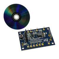
STEVAL-ILL021V1 STMicroelectronics, STEVAL-ILL021V1 Datasheet - Page 21

STEVAL-ILL021V1
Manufacturer Part Number
STEVAL-ILL021V1
Description
BOARD EVAL LCD BACKLIGHT LED7707
Manufacturer
STMicroelectronics
Specifications of STEVAL-ILL021V1
Design Resources
STEVAL-ILL021V1 Bill of Material STEVAL-ILL021V1 Schematic
Current - Output / Channel
85mA
Outputs And Type
6, Non-Isolated
Voltage - Output
36 V
Features
Dimmable, Extra 5V Output
Voltage - Input
4.5 ~ 36 V
Utilized Ic / Part
LED7707
Description/function
LCD backlight demonstration board
Operating Voltage
4.5 V to 36 V
Product
Display Modules
Core Chip
LED7707
No. Of Outputs
1
Output Voltage
36V
Dimming Control Type
PWM
Mcu Supported Families
LED7707
Lead Free Status / RoHS Status
Lead free by exemption / RoHS compliant by exemption
For Use With/related Products
LED7707
Other names
497-10044
Available stocks
Company
Part Number
Manufacturer
Quantity
Price
Company:
Part Number:
STEVAL-ILL021V1
Manufacturer:
STMicroelectronics
Quantity:
1
LED7707
5.2.2
5.3
PWM dimming
The brightness control of the LEDs is performed by a pulse-width modulation of the rows
current. When a PWM signal is applied to the DIM pin, the current generators are turned on
and off mirroring the DIM pin behavior. Actually, the minimum dimming duty-cycle depends
on the dimming frequency.
The real limit to the PWM dimming is the minimum on-time that can be managed for the
current generators; this minimum on-time is approximately 10 μs.
Thus, the minimum dimming duty-cycle depends on the dimming frequency according to the
following formula:
Equation 10
For example, at a dimming frequency of 1 kHz, 1% of dimming duty-cycle can be managed.
During the off-phase of the PWM signal the boost converter is paused and the current
generators are turned off. The output voltage can be considered almost constant because of
the relatively slow discharge of the output capacitor. During the start-up sequence (see
Section 5.1.3 on page 13
regardless of the applied dimming signal.
Figure 15. PWM dimming waveforms
Fault management
The main loop keeps the row having the lowest voltage drop regulated to about 700 mV.
This value slightly depends on the voltage across the remaining active rows. After the soft-
start sequence, all protections turn active and the voltage across the active current
generators is monitored to detect shorted LEDs.
) the dimming duty-cycle is forced to 100% to detect floating rows
D
DIM
,
min
=
10
μ
s
⋅
f
DIM
Operation description
10µs minimum on-time
10µs minimum on-time
21/47


