STEVAL-ILL021V1 STMicroelectronics, STEVAL-ILL021V1 Datasheet - Page 31
STEVAL-ILL021V1
Manufacturer Part Number
STEVAL-ILL021V1
Description
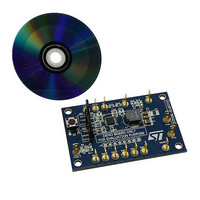
BOARD EVAL LCD BACKLIGHT LED7707
Manufacturer
STMicroelectronics
Specifications of STEVAL-ILL021V1
Design Resources
STEVAL-ILL021V1 Bill of Material STEVAL-ILL021V1 Schematic
Current - Output / Channel
85mA
Outputs And Type
6, Non-Isolated
Voltage - Output
36 V
Features
Dimmable, Extra 5V Output
Voltage - Input
4.5 ~ 36 V
Utilized Ic / Part
LED7707
Description/function
LCD backlight demonstration board
Operating Voltage
4.5 V to 36 V
Product
Display Modules
Core Chip
LED7707
No. Of Outputs
1
Output Voltage
36V
Dimming Control Type
PWM
Mcu Supported Families
LED7707
Lead Free Status / RoHS Status
Lead free by exemption / RoHS compliant by exemption
For Use With/related Products
LED7707
Other names
497-10044
Available stocks
Company
Part Number
Manufacturer
Quantity
Price
Company:

Part Number:
STEVAL-ILL021V1
Manufacturer:
STMicroelectronics
Quantity:
1


LED7707
6.3.3
6.4
6.4.1
6.4.2
6.4.3
Flywheel diode selection
The flywheel diode must be a Schottky type to minimize the losses. This component is
subject to an average current equal to the output one and must sustain a reverse voltage
equal to the maximum output rail voltage. Considering all the channels sinking 75 mA each
(i.e. 450 mA output current) and the maximum output voltage (36 V), the STP1L40M
(I
involving lower output voltage and/or lower output current.
Design example
In order to help the design of an application using the LED7707, in this section a simple
step-by-step design example is provided.
A possible application could be the LED backlight in a 17” LCD panel using the LED7707.
Here below the possible application conditions are listed:
●
●
●
Switching frequency setting
To reduce the number of the external components, the default switching frequency is
selected (660 kHz typ.) by connecting the FSW pin to AVCC pin.
However, in case a different switching frequency is required, a resistor from FSW pin and
ground can be connected, according to the equation (5) in section 4.1.5.
Row current setting
Considering the equation 9 in
Equation 24
The closest standard commercial value is 30 kΩ. The actual value of the row current will be
a little lower (61.7 mA).
Inductor choice
The boost section, as all DC-DC converters, can work in CCM (continuous conduction
mode) or in DCM (discontinuous conduction mode) depending on load current, input and
output voltage and other parameters, among which the inductor value.
In a boost converter it is usually preferable to work in DCM.
Once the load, the input and output voltage, and the switching frequency are fixed, the
inductor value defining the boundary between DCM and CCM operation can be calculated
as:
f,ave
V
4 strings of 42 white LEDs (60 mA) each (arranged in 6 rows, 7LEDs per row)
V
= 1 A, V
IN
F, LEDs
= 12 ± 10 %
= 3.5 V ± 200 mV
r
= 40 V) diode is a good choice. Smaller diodes can be used in applications
R
RILIM
Section 5.2.1
=
I
ROW
K
R
=
, the R
1850
60
mA
RILIM
V
=
resistor can be calculated as:
30
.
83
k
Ω
Application information
31/47
Related parts for STEVAL-ILL021V1
Image
Part Number
Description
Manufacturer
Datasheet
Request
R

Part Number:
Description:
BOARD EVAL FOR MEMS SENSORS
Manufacturer:
STMicroelectronics
Datasheet:

Part Number:
Description:
KIT DEV STARTER ST10F276Z5
Manufacturer:
STMicroelectronics
Datasheet:

Part Number:
Description:
BOARD EVAL HDMI $ VIDEO SWITCH
Manufacturer:
STMicroelectronics
Datasheet:

Part Number:
Description:
BOARD DEMO ACCELEROMETER DIL24
Manufacturer:
STMicroelectronics
Datasheet:

Part Number:
Description:
BOARD STLM75/STDS75/ST72F651
Manufacturer:
STMicroelectronics
Datasheet:

Part Number:
Description:
EVAL BOARD 3AXIS MEMS ACCELLRMTR
Manufacturer:
STMicroelectronics
Datasheet:

Part Number:
Description:
BOARD EVAL 8BIT MICRO + TDE1708
Manufacturer:
STMicroelectronics
Datasheet:

Part Number:
Description:
EVAL BOARD A/D TS4657
Manufacturer:
STMicroelectronics
Datasheet:

Part Number:
Description:
BOARD ADAPTER 20DIP LIS3LV02DL
Manufacturer:
STMicroelectronics
Datasheet:

Part Number:
Description:
BOARD DEMO STM8S207R6/LIS331DLH
Manufacturer:
STMicroelectronics
Datasheet:

Part Number:
Description:
STMicroelectronics [RIPPLE-CARRY BINARY COUNTER/DIVIDERS]
Manufacturer:
STMicroelectronics
Datasheet:
Part Number:
Description:
STMicroelectronics [LIQUID-CRYSTAL DISPLAY DRIVERS]
Manufacturer:
STMicroelectronics
Datasheet:
Part Number:
Description:
BOARD EVAL FOR MEMS SENSORS
Manufacturer:
STMicroelectronics
Datasheet: