MCP6S22DM-PICTL Microchip Technology, MCP6S22DM-PICTL Datasheet - Page 11
MCP6S22DM-PICTL
Manufacturer Part Number
MCP6S22DM-PICTL
Description
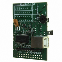
BOARD DEMO FOR MCP6S22
Manufacturer
Microchip Technology
Series
PICtail™r
Specifications of MCP6S22DM-PICTL
Channels Per Ic
2 - Dual
Amplifier Type
Programmable Gain
Output Type
Single-Ended, Rail-to-Rail
Slew Rate
22 V/µs
-3db Bandwidth
12MHz
Current - Output / Channel
30mA
Operating Temperature
-40°C ~ 85°C
Current - Supply (main Ic)
1mA
Voltage - Supply, Single/dual (±)
2.5 V ~ 5.5 V
Board Type
Fully Populated
Utilized Ic / Part
MCP6S22
Lead Free Status / RoHS Status
Contains lead / RoHS non-compliant
Available stocks
Company
Part Number
Manufacturer
Quantity
Price

Part Number:
MCP6S22DM-PICTL
Manufacturer:
MICROCHIP/微芯
Quantity:
20 000


2.1
2.2
2.3
2004 Microchip Technology Inc.
INTRODUCTION
FEATURES
GETTING STARTED
Chapter 2. MCP6S22 PGA PICtail Demo Board
The MCP6S22 PGA PICtail Demo Board is designed to demonstrate Microchip’s family
of Programmable Gain Amplifiers (PGAs) and uses the two-channel MCP6S22 PGA
device. An optical sensor circuit and potentiometer are used as voltage sources to the
PGA input channels. This demo board can be used to demonstrate firmware develop-
ment to program the PGA gains and channels using the PICkit 1 Flash Starter Kit.
In addition, the PGA gains and channels can be selected using the user interface DIP
switch. A PICmicro
to user configuration. This microcontroller also measures the PGA output voltage using
a 12-bit Analog-to-Digital Converter (ADC), with the measured data being transferred
to a Personal Computer (PC) using a Universal Serial Bus (USB) interface. The Pickit
1 Flash Starter Kit software is used as a Graphical User Interface (GUI) is used to
display the data on the PC.
This board is designed to evaluate the PGA with minimum PCB trace-induced noise or
crosstalk. It uses a four-layer board with solid ground and power layers. The placement
of each trace has been carefully considered so that the user can evaluate the PGA over
a wide frequency range.
The MCP6S22 PGA PICtail Demo Board has the following features:
• Demonstration of the MCP6S22 PGA
• 13-Bit Analog-to-Digital Converter (ADC) with SPI™ interface
• USB PIC16C745 microcontroller
• An optical sensor circuit connected to the PGA
• An adjustable voltage source using a thumb-wheel potentiometer connected to
• Four-layer PCB with separate ground and power supply planes for noise immunity
The MCP6S22 PGA PICtail Demo Board is used for evaluation and demonstration of
the PGA’s features. A block diagram of the demo board layout is shown in Figure 2-1.
The following procedure describes how to operate this demo board.
1. Install and run the GUI from the PC.
2. Connect the demo board to a PC using a USB cable.
3. Plug the jumpers for JP
4. The PGA output voltage will be graphically displayed on the PC.
5. Select the PGA gain and channel using the on-board DIP switch according to the
6. Press the READ push button switch to program the PGA.
the PGA
potentiometer voltage to the PGA input channels (CH0 and CH1).
configuration table printed on the demo board silk-screen.
®
microcontroller unit (MCU) is used to program the PGA according
DEMO BOARD USER’S GUIDE
1
and JP
MCP6S22 PGA PICTAIL™
2
to connect the optical sensor and the
DS51481A-page 7
Related parts for MCP6S22DM-PICTL
Image
Part Number
Description
Manufacturer
Datasheet
Request
R

Part Number:
Description:
Manufacturer:
Microchip Technology Inc.
Datasheet:
Part Number:
Description:
Manufacturer:
Microchip Technology Inc.
Datasheet:
Part Number:
Description:
Manufacturer:
Microchip Technology Inc.
Datasheet:
Part Number:
Description:
Manufacturer:
Microchip Technology Inc.
Datasheet:
Part Number:
Description:
Manufacturer:
Microchip Technology Inc.
Datasheet:
Part Number:
Description:
Manufacturer:
Microchip Technology Inc.
Datasheet:
Part Number:
Description:
Manufacturer:
Microchip Technology Inc.
Datasheet:
Part Number:
Description:
Manufacturer:
Microchip Technology Inc.
Datasheet: