MCP6S22DM-PICTL Microchip Technology, MCP6S22DM-PICTL Datasheet - Page 13
MCP6S22DM-PICTL
Manufacturer Part Number
MCP6S22DM-PICTL
Description
BOARD DEMO FOR MCP6S22
Manufacturer
Microchip Technology
Series
PICtail™r
Specifications of MCP6S22DM-PICTL
Channels Per Ic
2 - Dual
Amplifier Type
Programmable Gain
Output Type
Single-Ended, Rail-to-Rail
Slew Rate
22 V/µs
-3db Bandwidth
12MHz
Current - Output / Channel
30mA
Operating Temperature
-40°C ~ 85°C
Current - Supply (main Ic)
1mA
Voltage - Supply, Single/dual (±)
2.5 V ~ 5.5 V
Board Type
Fully Populated
Utilized Ic / Part
MCP6S22
Lead Free Status / RoHS Status
Contains lead / RoHS non-compliant
Available stocks
Company
Part Number
Manufacturer
Quantity
Price

Part Number:
MCP6S22DM-PICTL
Manufacturer:
MICROCHIP/微芯
Quantity:
20 000


2.4
2004 Microchip Technology Inc.
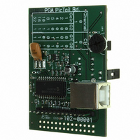
MCP6S22 PGA PICtail™ Demo Board User’s Guide
DEMO BOARD DESCRIPTION
The following sections describe each element of this demo board in further detail.
2.4.1
This demo board can be powered using the USB interface, an external voltage source
or the PICkit 1 Flash Starter Kit. Power to the digital and analog components is
separated in order to avoid digital crosstalk to the analog components; particularly
noise from the fast transient edges of serial data signals that are riding on the USB
power line. In order to minimize high-frequency noise, a two-pole Resistor-Capacitor
(RC) filter network is used to attenuate the noise. This filtered source is regulated using
Microchip’s TC55 voltage regulator (U3). The TC55 regulates the +5V supply from the
USB source to +4.1V. This regulated voltage (V
includes the MCP6S22 PGA (U5), MCP3301 ADC (U
potentiometer (VR
and the pull-up resistors that are connected to the PICmicro microcontroller I/O lines.
To minimize ground noise on the analog components, the Printed Circuit Board (PCB)
has four layers. The top layer is for analog circuits and the bottom layer is for digital
circuits. The two layers in the middle are the power and ground planes.
The I/O lines connected to the PGA have a resistor voltage-divider network. Since the
PICmicro microcontroller is powered by a +5V supply and the PGA is powered with
+4.1V supply, there is an approximate 1V difference in the serial communication level.
This could trigger the PGA’s Electrostatic Discharge (ESD) protection diodes or
damage the device. Therefore, a voltage divider network is used to lower the serial
communication voltage level to 4V.
2.4.2
This demo board uses the dual-channel MCP6S22 PGA (U5) to demonstrate the PGA
functions. There are two on-board circuits that can be used to demonstrate the PGA
functions. These circuits are an optical sensor (D
potentiometer (VR
JP
JP
The user can change the voltage to the input channels of the PGA and observe the
PGA output voltage on the GUI or an oscilloscope. The thumb-wheeled potentiometer
can be used to quickly demonstrate the PGA’s gain function by adjusting the input
voltage and changing the gain. However, the optical sensor circuit requires a change
in the ambient light. The change in ambient light results in a change in voltage.
Therefore, the photodiode on the PCB needs to be pointed towards higher light
intensity. The PGA can be used to gain up the voltage change from either sensor
circuit, thereby utilizing the full input range of the ADC.
The user can also develop a circuit on the prototype development area and connect the
circuit to the PGA input channels (refer to Section 2.4.7 “Using the Prototype Area”
for soldering guidance). In this case, the jumpers on JP
disconnected.
2
1
Caution: The jumpers need to be removed when connecting circuits using
. Pins 1 and 2 of JP
connect the potentiometer to Channel 1 of the PGA.
Power
PGA Input Channels and On-Board Circuits
the prototype area or the SMA (SPC 10611) connectors.
1
1
). The unregulated +5V supply (V
). The two input channels are connected to the jumpers JP
2
connect the optical sensor to Channel 0, while pins 1 and 2 of
REG
2
) and a thumb-wheeled
) powers the analog devices which
4
DD
), photodiode circuit (D
) powers the PICmicro MCU
1
and JP
2
need to be
DS51481A-page 9
2
) and the
1
and
Related parts for MCP6S22DM-PICTL
Image
Part Number
Description
Manufacturer
Datasheet
Request
R

Part Number:
Description:
Manufacturer:
Microchip Technology Inc.
Datasheet:
Part Number:
Description:
Manufacturer:
Microchip Technology Inc.
Datasheet:
Part Number:
Description:
Manufacturer:
Microchip Technology Inc.
Datasheet:
Part Number:
Description:
Manufacturer:
Microchip Technology Inc.
Datasheet:
Part Number:
Description:
Manufacturer:
Microchip Technology Inc.
Datasheet:
Part Number:
Description:
Manufacturer:
Microchip Technology Inc.
Datasheet:
Part Number:
Description:
Manufacturer:
Microchip Technology Inc.
Datasheet:
Part Number:
Description:
Manufacturer:
Microchip Technology Inc.
Datasheet: