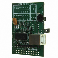
MCP6S22DM-PICTL Microchip Technology, MCP6S22DM-PICTL Datasheet - Page 14

MCP6S22DM-PICTL
Manufacturer Part Number
MCP6S22DM-PICTL
Description
BOARD DEMO FOR MCP6S22
Manufacturer
Microchip Technology
Series
PICtail™r
Specifications of MCP6S22DM-PICTL
Channels Per Ic
2 - Dual
Amplifier Type
Programmable Gain
Output Type
Single-Ended, Rail-to-Rail
Slew Rate
22 V/µs
-3db Bandwidth
12MHz
Current - Output / Channel
30mA
Operating Temperature
-40°C ~ 85°C
Current - Supply (main Ic)
1mA
Voltage - Supply, Single/dual (±)
2.5 V ~ 5.5 V
Board Type
Fully Populated
Utilized Ic / Part
MCP6S22
Lead Free Status / RoHS Status
Contains lead / RoHS non-compliant
Available stocks
Company
Part Number
Manufacturer
Quantity
Price
Part Number:
MCP6S22DM-PICTL
Manufacturer:
MICROCHIP/微芯
Quantity:
20 000
MCP6S22 PGA PICtail™ Demo Board User’s Guide
DS51481A-page 10
2.4.3
The PGA gains and channels can be configured using the DIP switch (S
momentary push button switch (S
Ch0/1 to the ‘0’ or ‘1’ position according to the configuration table provided on the demo
board silk-screen and momentarily pressing the READ push button switch to configure
the PGA. The configuration table is also shown in Table 2-1 and Table 2-2.
TABLE 2-1:
TABLE 2-2:
These configuration switches cannot be used to program the PGA if this demo board
is connected to the PICkit 1 Flash Starter Kit (Refer to Section 2.4.6 “PGA Interface
to PICkit 1 Flash Starter Kit” for further explanation).
2.4.4
The MCP6S22 PGA output is connected to a MCP3301 13-bit ADC with RC
anti-aliasing filter. The ADC continuously measures the PGA output voltage and
transmits the data to the PIC16C745 using an SPI bus interface. The measured data is
transmitted to the PC via the USB port for display. The PGA output pin is also
connected to a test point, allowing the user to connect an oscilloscope probe and
measure the PGA output.
When the scope probe is connected, the effect of the probe on the PGA output needs
to be considered. The probe capacitance introduces a capacitive load to the PGA, so
the effects of capacitive load needs to be considered (refer to the MCP6S22 data sheet
(DS21117) for further details). In addition to the probe capacitance, a long ground lead
from the scope probe to the demo board creates a ground loop and compromises the
PGA performance. Therefore, the probe ground lead needs to be as short as possible.
It is recommended that the user solder SMA connectors in the space provided
(Figure 2-2) and use shielded cables to connect the input and output signals from an
external voltage source, and to an oscilloscope. This ensures proper demonstration of
the MCP6S22 PGA performance.
Gain
PGA Gain and Channel Selection
Measuring the PGA Output
10
16
32
1
2
4
5
8
DIP SWITCH CONFIGURATION TO PROGRAM PGA GAIN
DIP SWITCH CONFIGURATION TO PROGRAM PGA CHANNEL
Channel
0
1
G2
0
0
0
0
1
1
1
1
1
). The user can slide the G2, G1, G0 switches and
G1
0
0
1
1
0
0
1
1
2004 Microchip Technology Inc.
Ch 0/1
0
1
2
G0
) and the
0
1
0
1
0
1
0
1


