MCP6S22DM-PICTL Microchip Technology, MCP6S22DM-PICTL Datasheet - Page 15
MCP6S22DM-PICTL
Manufacturer Part Number
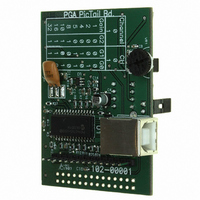
MCP6S22DM-PICTL
Description
BOARD DEMO FOR MCP6S22
Manufacturer
Microchip Technology
Series
PICtail™r
Specifications of MCP6S22DM-PICTL
Channels Per Ic
2 - Dual
Amplifier Type
Programmable Gain
Output Type
Single-Ended, Rail-to-Rail
Slew Rate
22 V/µs
-3db Bandwidth
12MHz
Current - Output / Channel
30mA
Operating Temperature
-40°C ~ 85°C
Current - Supply (main Ic)
1mA
Voltage - Supply, Single/dual (±)
2.5 V ~ 5.5 V
Board Type
Fully Populated
Utilized Ic / Part
MCP6S22
Lead Free Status / RoHS Status
Contains lead / RoHS non-compliant
Available stocks
Company
Part Number
Manufacturer
Quantity
Price

Part Number:
MCP6S22DM-PICTL
Manufacturer:
MICROCHIP/微芯
Quantity:
20 000


2004 Microchip Technology Inc.
MCP6S22 PGA PICtail™ Demo Board User’s Guide
2.4.5
When the MCP6S22 PGA PICtail Demo Board is operating in “stand-alone” mode (not
connected to the PICkit 1 Flash Starter Kit), the PIC16C745 microcontroller (U
performs three major functions: (1) It communicates to the host PC via the USB port
(J
and S
order to read the ADC’s digitized output voltage.
Initially, the microcontroller establishes communication with the host PC via the USB
port. It then commands the ADC to perform a conversion and reads the data. This data
is then transferred to the host PC. This routine continues until the user momentarily
pushes the READ push button switch. When the user requests the read, the PICmicro
microcontroller reads the DIP switch configuration and programs the PGA’s gain and
channel settings accordingly using the SPI interface. The routine then continues to
transmit data from the ADC to the host PC.
Note that it is not necessary to connect the USB interface to a PC to program the PGA.
The demo board can be powered using an external +5V source and the user can
program the PGA using the READ push button switch. In this case, an oscilloscope
needs to be used to measure the output voltage.
2.4.6
This MCP6S22 PGA PICtail Demo Board can be connected to a PICkit 1 Flash Starter
Kit using the 14-pin header. In this configuration, the MCP6S22 PGA PICtail Demo
Board can be used as an evaluation tool for most of the 14-pin Flash PICmicro
microcontrollers. The user can develop firmware to change the PGA gains and
channels using this demo board.
A demo firmware has been provided that can be programmed in a 14-pin PICmicro
microcontroller (PIC16F676) using the PICkit 1 Flash Starter Kit. The user can change
the PGA gains and channels using the available push button switch (SW1) and
potentiometer (VR
turning the potentiometer to the left or right changes the channel. The gain setting is
displayed on the on-board LEDs in binary format. In addition, this firmware uses the
internal 10-bit ADC to measure the PGA output voltage. The data is transmitted to the
PC for display in strip-chart format using the PICkit 1 Flash Starter Kit software.
Only 5 pins of the 14-pin header are connected for I/O. Four of the five lines (RC3, RC4,
RC5 and RC2) are connected to the SPI pins of the PGA and ADC (SCK, SData and
CS) pins. The fifth line (RC0) is connected to the PGA output voltage pin. This line is
selected specifically for 14-pin PICmicro microcontrollers with an internal ADC. Note
that if the PICkit 1 Flash Starter Kit is being used, the PICmicro microcontroller RC0 I/O
pin is configured as an output. This will load down the PGA’s output and the perfor-
mance will be degraded. Therefore, be sure to configure the PICmicro microcontroller
RC0 I/O pin as a high-impedance A/D input pin.
Since the PICkit 1 Flash Starter Kit is powered via the USB port, the voltage level of the
SPI line is +5V, which is higher than the PGA supply voltage. Therefore, a voltage
divider network (R
MCP6S22 to lower the communication voltage level. Refer to Section 2.4.1 “Power”
for further explanation.
1
); (2) programs the PGA according to the user-configured DIP switch settings (S
2
); and (3) communicates with the MCP3301 ADC (U
PICmicro Microcontroller Functions
PGA Interface to PICkit 1 Flash Starter Kit
1
11
). The push button allows the user to step through the gains, while
-R
16
, R
24
, R
25
) is implemented between the PIC16C745 and
4
) via the SPI interface in
DS51481A-page 11
1
)
1
Related parts for MCP6S22DM-PICTL
Image
Part Number
Description
Manufacturer
Datasheet
Request
R

Part Number:
Description:
Manufacturer:
Microchip Technology Inc.
Datasheet:
Part Number:
Description:
Manufacturer:
Microchip Technology Inc.
Datasheet:
Part Number:
Description:
Manufacturer:
Microchip Technology Inc.
Datasheet:
Part Number:
Description:
Manufacturer:
Microchip Technology Inc.
Datasheet:
Part Number:
Description:
Manufacturer:
Microchip Technology Inc.
Datasheet:
Part Number:
Description:
Manufacturer:
Microchip Technology Inc.
Datasheet:
Part Number:
Description:
Manufacturer:
Microchip Technology Inc.
Datasheet:
Part Number:
Description:
Manufacturer:
Microchip Technology Inc.
Datasheet: