EVAL-AD7150EBZ Analog Devices Inc, EVAL-AD7150EBZ Datasheet - Page 23
EVAL-AD7150EBZ
Manufacturer Part Number
EVAL-AD7150EBZ
Description
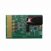
BOARD EVAL FOR AD7150
Manufacturer
Analog Devices Inc
Datasheet
1.AD7150BRMZ.pdf
(28 pages)
Specifications of EVAL-AD7150EBZ
Sensor Type
Touch, Capacitive
Interface
I²C
Voltage - Supply
2.7 V ~ 3.6 V
Embedded
No
Utilized Ic / Part
AD7150
Lead Free Status / RoHS Status
Lead free / RoHS Compliant
Sensitivity
-
Sensing Range
-
Lead Free Status / Rohs Status
Supplier Unconfirmed
Available stocks
Company
Part Number
Manufacturer
Quantity
Price
Company:

Part Number:
EVAL-AD7150EBZ
Manufacturer:
Analog Devices Inc
Quantity:
135


HARDWARE DESIGN CONSIDERATIONS
OVERVIEW
The AD7150 is an interface to capacitive sensors.
On the input side, the sensor (C
between the AD7150 EXC and CIN pins. The way it is
connected and the electrical parameters of the sensor
connection, such as parasitic resistance or capacitance, can
affect the system performance. Therefore, any circuit with
additional components in the capacitive front end, such as
overvoltage protection, has to be carefully designed considering
the AD7150 specified limits and information provided in this
section.
On the output side, the AD7150 can work as a standalone
device, using the power-up default register settings and flagging
the result on digital outputs. Alternatively, the AD7150 can be
interfaced to a microcontroller via the 2-wire serial interface,
offering flexibility by overwriting the AD7150 register values
from the host with a user-specific setup.
PARASITIC CAPACITANCE TO GROUND
The CDC architecture used in the AD7150 measures the
capacitance, C
pin. In theory, any capacitance C
the CDC result (see Figure 44).
The practical implementation of the circuitry in the chip
implies certain limits, and the result is gradually affected by
capacitance to ground (see Table 1 for information about the
allowed capacitance to GND for CIN and information about
excitation).
See Figure 4 to Figure 9.
C
C
GND1
GND2
Figure 44. Parasitic Capacitance to Ground
X
, connected between the EXC pin and the CIN
C
X
EXC
CIN
X
GND
) can be connected directly
to ground should not affect
CDC
DATA
Rev. 0 | Page 23 of 28
PARASITIC RESISTANCE TO GROUND
The AD7150 CDC result is affected by a leakage current from
C
The equivalent resistance between C
maximized (see Figure 45).
See Figure 10 to Figure 13.
PARASITIC PARALLEL RESISTANCE
The AD7150 CDC measures the charge transfer between the
EXC and CIN pins. Any resistance connected in parallel to the
measured capacitance C
resistance of the sensor, also transfers charge. Therefore, the
parallel resistor is seen as an additional capacitance in the
output data. The equivalent parallel capacitance (or error
caused by the parallel resistance) can be approximately
calculated as
where R
frequency.
See Figure 15.
X
to ground; therefore, C
R
R
C
GND1
GND2
C
P
P
X
=
is the parallel resistance and f
R
R
P
P
EXC
Figure 45. Parasitic Resistance to Ground
×
C
CIN
Figure 46. Parasitic Parallel Resistance
X
f
1
EXC
CIN
EXC
×
4
X
(see Figure 46), such as the parasitic
X
should be isolated from the ground.
X
CDC
and ground should be
EXC
CDC
is the excitation
DATA
AD7150
DATA
Related parts for EVAL-AD7150EBZ
Image
Part Number
Description
Manufacturer
Datasheet
Request
R


Part Number:
Description:
BOARD EVAL FOR SI270X-A
Manufacturer:
Silicon Laboratories Inc
Datasheet:

Part Number:
Description:
BUCK CONV REF DESIGN KIT IP1201
Manufacturer:
International Rectifier
Datasheet:
Part Number:
Description:
BOARD DEMO SYNC DUAL BUCK CNVTER
Manufacturer:
International Rectifier
Datasheet:
Part Number:
Description:
BOARD DEMO SYNC BUCK CONVETER
Manufacturer:
International Rectifier
Datasheet:

Part Number:
Description:
EVALBOARD/EB Omnidirectional microphone - Analog
Manufacturer:
Analog Devices
Datasheet:
Part Number:
Description:
EVALBOARD/EB Omnidirectional microphone - Analog
Manufacturer:
Analog Devices
Datasheet:


Part Number:
Description:
BOARD EVAL LED DRIVER LT3756
Manufacturer:
Linear Technology
Datasheet:

Part Number:
Description:
BOARD EVAL FOR AD7741/7742
Manufacturer:
Analog Devices Inc
Datasheet:

Part Number:
Description:
±1.7g Dual-Axis IMEMS Accelerometer Evaluation Board
Manufacturer:
Analog Devices Inc
Datasheet:

Part Number:
Description:
IC MULTIPLIER ANALOG 8-SOIC T/R
Manufacturer:
Analog Devices Inc
Datasheet:

Part Number:
Description:
IC ANALOG MULTIPLIER 8-DIP
Manufacturer:
Analog Devices Inc
Datasheet:
Part Number:
Description:
IC ANALOG MULTIPLIER 8-SOIC
Manufacturer:
Analog Devices Inc
Datasheet:
Part Number:
Description:
IC ANALOG MULTIPLIER 8-DIP
Manufacturer:
Analog Devices Inc
Datasheet: