DV164122 Microchip Technology, DV164122 Datasheet - Page 119
DV164122
Manufacturer Part Number
DV164122
Description
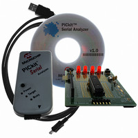
ANALYZER SRL PICKIT W/DEMO BOARD
Manufacturer
Microchip Technology
Series
PICkit™r
Type
MCUr
Specifications of DV164122
Contents
PICkit™ Serial Analyzer, 28-pin Demo Board, USB Cable, and Software with Documentation CD
Processor To Be Evaluated
PIC16F886
Interface Type
USB
Silicon Manufacturer
Microchip
Kit Application Type
Interface
Application Sub Type
USB
Silicon Family Name
PIC16F
Kit Contents
PICkit Serial Analyzer, Demo Board, USB Cable, Software
Rohs Compliant
Yes
Lead Free Status / RoHS Status
Not applicable / Not applicable
For Use With/related Products
PIC16F886
For Use With
PKSERIAL-SPI1 - BOARD DEMO PICKIT SERIAL SPIPKSERIAL-I2C1 - BOARD DEMO PICKIT SERIAL I2C
Lead Free Status / Rohs Status
Lead free / RoHS Compliant
Other names
Q3260228
Available stocks
Company
Part Number
Manufacturer
Quantity
Price
Company:

Part Number:
DV164122
Manufacturer:
Microchip Technology
Quantity:
135
Company:
Part Number:
DV164122
Manufacturer:
MICROCHIP
Quantity:
12 000


© 2007 Microchip Technology Inc.
28-Pin Demo Board I
B.7.3
The ADC Display begins by displaying hex values 0x0A, 0x0D and 0x0C in sequence
to signify “ADC” test.
After the opening display sequence, the LEDs displays the Most Significant 4 bits of the
ADC result measuring channel AN0 (potentiometer RP1). As RP1 is manually turned
from one extreme to the other, the LED display should range from binary 0000 to 1111.
The firmware must be forced from this mode by command or Reset.
B.7.4
The RTC Display displays the Least Significant 4 bits of EXEC_REG_02 (RTC SEC-
ONDS). The LEDs should be seen to increment once per second in a binary progres-
sion (0x0-0xF) three times, then (0x0-0xB) once as the RTC SECONDS value
increments from 0x00 to 0x3B (59 decimal). The firmware must be forced from this
mode by command or Reset.
B.7.5
This feature displays the state of the 4 signal pins on the communications connector.
LED1: PIN 1 (AUX1)
LED2: PIN 4 (SDA)
LED3: PIN 5 (SCL)
LED4: PIN 6 (AUX2)
Normally, LED2 and LED3 should be illuminated if the I
the SCK is not held low. The firmware must be forced from this mode by command or
Reset.
B.7.6
The RESET Display is executed on Reset/power-up or by command. The sequence is
a series of individual displays as follows:
1. PING-PONG display: cycles: 2 (i.e., LED1,2,3,4,3,2,1,2,3,4,3,2,1)
2. Blink all LEDs in unison: cycles: 1 (i.e., 1 sec OFF, 1 sec ON, 1 sec OFF)
3. ADC display (described above): cycles: perpetual
B.7.7
Blink all LEDs in unison at 1-second intervals (i.e., 1 sec OFF, 1 sec ON, 1 sec
OFF),...This feature uses time based on the Timer1 low-power oscillator and external
32 kHz tuning fork crystal.
ADC Display
RTC Display
Communications Connector Display
RESET Display
1 Second Blink
2
C™ Demonstration Firmware
2
C bus has active pull-ups and
DS51647A-page 113
Related parts for DV164122
Image
Part Number
Description
Manufacturer
Datasheet
Request
R

Part Number:
Description:
Manufacturer:
Microchip Technology Inc.
Datasheet:
Part Number:
Description:
Manufacturer:
Microchip Technology Inc.
Datasheet:
Part Number:
Description:
Manufacturer:
Microchip Technology Inc.
Datasheet:
Part Number:
Description:
Manufacturer:
Microchip Technology Inc.
Datasheet:
Part Number:
Description:
Manufacturer:
Microchip Technology Inc.
Datasheet:
Part Number:
Description:
Manufacturer:
Microchip Technology Inc.
Datasheet:
Part Number:
Description:
Manufacturer:
Microchip Technology Inc.
Datasheet:
Part Number:
Description:
Manufacturer:
Microchip Technology Inc.
Datasheet: