DV164122 Microchip Technology, DV164122 Datasheet - Page 92
DV164122
Manufacturer Part Number
DV164122
Description
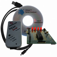
ANALYZER SRL PICKIT W/DEMO BOARD
Manufacturer
Microchip Technology
Series
PICkit™r
Type
MCUr
Specifications of DV164122
Contents
PICkit™ Serial Analyzer, 28-pin Demo Board, USB Cable, and Software with Documentation CD
Processor To Be Evaluated
PIC16F886
Interface Type
USB
Silicon Manufacturer
Microchip
Kit Application Type
Interface
Application Sub Type
USB
Silicon Family Name
PIC16F
Kit Contents
PICkit Serial Analyzer, Demo Board, USB Cable, Software
Rohs Compliant
Yes
Lead Free Status / RoHS Status
Not applicable / Not applicable
For Use With/related Products
PIC16F886
For Use With
PKSERIAL-SPI1 - BOARD DEMO PICKIT SERIAL SPIPKSERIAL-I2C1 - BOARD DEMO PICKIT SERIAL I2C
Lead Free Status / Rohs Status
Lead free / RoHS Compliant
Other names
Q3260228
Available stocks
Company
Part Number
Manufacturer
Quantity
Price
Company:

Part Number:
DV164122
Manufacturer:
Microchip Technology
Quantity:
135
Company:
Part Number:
DV164122
Manufacturer:
MICROCHIP
Quantity:
12 000


PICkit™ Serial Analyzer User’s Guide
DS51647A-page 86
The script (above) is interpreted as follows. TAG 0x81 instructs the COMM module to
generate an I
following the start – 0xA8 and 0x01. The first byte is the I
write/read bit Reset) and a data/command byte of 0x01. The COMM module does not
place any significance on the value of the data bytes but merely transmits them ‘blindly’
– as instructed. The next TAG 0x83 instructs the COMM module to issue a Restart bit
on the I
be transmitted. Here again, the COMM module does not interpret the data – the I
slave will interpret 0xA9 as an address with write/read bit set. TAG 0x89 followed by
data byte 0x01 instructs the COMM module to attempt to read 1 byte from the slave
then issue a NACK on the bus. Finally, an I
The resulting I
[START][A8][01][RESTART][A9][data byte received][STOP]
As the script is executed, a data stream will be developed using TAGs/CDATA
(described in Table 9-19) and returned to the host software via CBUF2.
TABLE 9-19:
CDATA
TAG/
0x8A
0x80
0x81
0x82
0x83
0x84
0x85
0x86
0x87
0x88
0x89
2
C bus. TAG and data bytes - 0x84, 0x01, 0xA9 – will cause 1 byte (0xA9) to
LEN
1
1
1
1
1
1
1
2
2
2
2
2
C ‘Start’ bit on the I
2
C transaction looks like this on the bus:
I
2
I
I
I
I
I
I
I
I
I
I
I
2
2
2
2
2
2
2
2
2
2
2
CM ‘DATA’ TAG BYTES
CM_EVENT_START_TX
CM_EVENT_STOP_TX
CM_EVENT_RESTART_TX
CM_EVENT_ACK_TX
CM_EVENT_NACK_TX
CM_EVENT_ACK_RX
CM_EVENT_NACK_RX
CM_EVENT_BYTE_TX
CM_EVENT_BYTE_RX
CM_EVENT_XACT_ERR
CM_EVENT_STATUS_ERR
Name
2
C bus. TAG 0x84 indicates 2 bytes will be transmitted
2
C ‘Stop’ bit is issued according to tag 0x82.
Start bit event
Stop bit event
Restart bit event
ACK bit event
NACK bit event
ACK bit event
NACK bit event
BYTE transmit
BYTE transmit
transaction error
status error
0
0
0
0
0
0
0
0
1
0
1
0
1
0
1
CDATA-TAG
CDATA-TAG
CDATA-TAG
CDATA-TAG
CDATA-TAG
CDATA-TAG
CDATA-TAG
CDATA-TAG
data
CDATA-TAG
data
CDATA-TAG
error byte
CDATA-TAG
error byte
2
C slave address (with
© 2007 Microchip Technology Inc.
Description
2
C
Related parts for DV164122
Image
Part Number
Description
Manufacturer
Datasheet
Request
R

Part Number:
Description:
Manufacturer:
Microchip Technology Inc.
Datasheet:
Part Number:
Description:
Manufacturer:
Microchip Technology Inc.
Datasheet:
Part Number:
Description:
Manufacturer:
Microchip Technology Inc.
Datasheet:
Part Number:
Description:
Manufacturer:
Microchip Technology Inc.
Datasheet:
Part Number:
Description:
Manufacturer:
Microchip Technology Inc.
Datasheet:
Part Number:
Description:
Manufacturer:
Microchip Technology Inc.
Datasheet:
Part Number:
Description:
Manufacturer:
Microchip Technology Inc.
Datasheet:
Part Number:
Description:
Manufacturer:
Microchip Technology Inc.
Datasheet: