DV164122 Microchip Technology, DV164122 Datasheet - Page 35
DV164122
Manufacturer Part Number
DV164122
Description
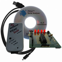
ANALYZER SRL PICKIT W/DEMO BOARD
Manufacturer
Microchip Technology
Series
PICkit™r
Type
MCUr
Specifications of DV164122
Contents
PICkit™ Serial Analyzer, 28-pin Demo Board, USB Cable, and Software with Documentation CD
Processor To Be Evaluated
PIC16F886
Interface Type
USB
Silicon Manufacturer
Microchip
Kit Application Type
Interface
Application Sub Type
USB
Silicon Family Name
PIC16F
Kit Contents
PICkit Serial Analyzer, Demo Board, USB Cable, Software
Rohs Compliant
Yes
Lead Free Status / RoHS Status
Not applicable / Not applicable
For Use With/related Products
PIC16F886
For Use With
PKSERIAL-SPI1 - BOARD DEMO PICKIT SERIAL SPIPKSERIAL-I2C1 - BOARD DEMO PICKIT SERIAL I2C
Lead Free Status / Rohs Status
Lead free / RoHS Compliant
Other names
Q3260228
Available stocks
Company
Part Number
Manufacturer
Quantity
Price
Company:

Part Number:
DV164122
Manufacturer:
Microchip Technology
Quantity:
135
Company:
Part Number:
DV164122
Manufacturer:
MICROCHIP
Quantity:
12 000


© 2007 Microchip Technology Inc.
COMM I
Select the desired I
FIGURE 4-2:
EVENT MARKERS
• Abrt Mac Exe – Enable event marker: abort ‘macro’ execution
• Macro Loop – Enable event marker: top of ‘macro’ loop
• Mac Lp 65536 – Enable event marker: ‘macro’ loop count overflow (i.e., 65536)
• Mac Lp Done – Enable event marker: ‘macro’ loop iterations complete
• Timeout Timer1 – Enable event marker: Timer1 expired
• Timeout Timer2 – Enable event marker: Timer2 expired
• Status Error – Enable event marker: change in status byte
• Start Bit – Enable event marker – Start bit
• Stop Bit – Enable event marker – Stop bit
• Restart Bit – Enable event marker – Restart bit
• Ack/Nack TX – Enable event marker – Ack or Nack byte transmit
• Ack/Nack RX – Enable event marker – Ack or Nack byte received
• Write Byte – Enable event marker – write byte
• Read Byte – Enable event marker – read byte
• TX Error – Enable event marker – TX error
• Status Error – Enable event marker – change in I
ADVANCED OPTIONS
• Disable LED2 Default – Disable default LED2 behavior (LED2 = Yellow ‘Target’
• Disable LED1 Default – Disable default LED1 behavior (LED1 = Red ‘Busy’ LED)
• Enable Switch Test – Enable low level switch test:
• AUX1 Default State – AUX1 communication line – default state (0 | 1)
• AUX2 Default State – AUX2 communication line – default state (0 | 1)
• AUX1 Direction – AUX1 communication line – direction: 1: input, 0: output
LED)
- Switch Off (not depressed) – blink LED1, LED2 off
- Switch ON (depressed) – blink LED2, LED1 off
2
CM BIT RATE
2
C bus bit rate using the drop down box.
I
VIEW
2
C™ CONFIGURE COMMUNICATIONS MODE – ADVANCED
I
2
C™ Master Communications
2
C status byte
DS51647A-page 29
Related parts for DV164122
Image
Part Number
Description
Manufacturer
Datasheet
Request
R

Part Number:
Description:
Manufacturer:
Microchip Technology Inc.
Datasheet:
Part Number:
Description:
Manufacturer:
Microchip Technology Inc.
Datasheet:
Part Number:
Description:
Manufacturer:
Microchip Technology Inc.
Datasheet:
Part Number:
Description:
Manufacturer:
Microchip Technology Inc.
Datasheet:
Part Number:
Description:
Manufacturer:
Microchip Technology Inc.
Datasheet:
Part Number:
Description:
Manufacturer:
Microchip Technology Inc.
Datasheet:
Part Number:
Description:
Manufacturer:
Microchip Technology Inc.
Datasheet:
Part Number:
Description:
Manufacturer:
Microchip Technology Inc.
Datasheet: