DM163022 Microchip Technology, DM163022 Datasheet - Page 19
DM163022
Manufacturer Part Number
DM163022
Description
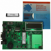
BOARD DEMO PICDEM-2 PLUS
Manufacturer
Microchip Technology
Type
MCUr
Specifications of DM163022
Contents
Board, CD, Sample Part
Processor To Be Evaluated
PIC 16 and PIC 18
Interface Type
RS-232
Silicon Manufacturer
Microchip
Core Architecture
PIC
Core Sub-architecture
PIC16, PIC18
Silicon Core Number
PIC16F, PIC18F
Silicon Family Name
PIC16F8xx, PIC18F4xxx
Rohs Compliant
NA
Lead Free Status / RoHS Status
Lead free / RoHS Compliant
For Use With/related Products
PICDEM 2 Plus
Lead Free Status / Rohs Status
Lead free / RoHS Compliant
Other names
DM163022R
DM163022R
DM163022R
Available stocks
Company
Part Number
Manufacturer
Quantity
Price
Company:

Part Number:
DM163022
Manufacturer:
Microchip Technology
Quantity:
135
Company:
Part Number:
DM163022-1
Manufacturer:
MICROCHIP
Quantity:
12 000


TABLE 2-2:
© 2005 Microchip Technology Inc.
Legend: S = Jumper is shorted (Closed)
Note 1: The MCP2120’s RX signal is either connected via JMP1 or JP6 (but not both at the same time).
JP1C:JP2C To connect TXIR/RXIR of MCP2122 to TXD/RXD of
JP1A:JP2A To connect TXIR/RXIR of MCP2122 to TXD/RXD of
JP1B:JP2B To connect TXIR/RXIR of MCP2122 to TXD/RXD of
Jumper #
JMP1
JMP2
JMP3
JP1
JP2
JP3
JP4
JP5
JP6
JP7
2: The MCP2120’s TX signal is either connected via JMP3 or JP7 (but not both at the same time).
U5 (HSDL 3000)
S = TXIR/RXIR connected to TXD/RXD
O = TXIR/RXIR Not connected to TXD/RXD
U5 (TFDU 4100)
S = TXIR/RXIR connected to TXD/RXD
O = TXIR/RXIR Not connected to TXD/RXD
U5 (TFDU 4300)
S = TXIR/RXIR connected to TXD/RXD
O = TXIR/RXIR Not connected to TXD/RXD
Hardware control of Header RA0 signal and MCP2120
BAUD0 signal
S = Signal Connected to V
O = Signal Connected to V
Hardware control of Header RA1 signal and MCP2120
BAUD1 signal
S = Signal Connected to V
O = Signal Connected to V
Hardware control of Header RC0 signal and MCP2120
BAUD2 signal
S = Signal Connected to V
O = Signal Connected to V
Hardware control of Header RC1 signal and MCP2120
MODE signal
S = Signal Connected to V
O = Signal Connected to V
Hardware control of Header RA3 signal and MCP2120 EN
signal
S = Signal Connected to V
O = Signal Connected to V
Connects MCP2120 RX signal to either Header 1’s RX
signal or Header 2/Header 3 RX signals
Connects MCP2120 RX signal to Header 1’s TX signal
Connects MCP2120 16XCLK signal to either Header 1’s
16XCLK signal or to Header 2/Header 3’s 16XCLK signals
Connects MCP2120 TX signal to Header 1’s TX
signal or Header 2/Header 3 TX signals
Connects MCP2120 TX signal to Header 1’s RX
signal
JUMPER DESCRIPTIONS AND SETTINGS
A description of the MCP212X Developer’s Daughter Board jumpers is given in
Table 2-2.
Description
SS
SS
SS
SS
SS
DD
DD
DD
DD
DD
O = Jumper is Open
Installation and Operation
By default not installed.
By default not installed.
By default not installed. PCB traces
short these jumpers (bottom of PCB)
Note 1
Used when the MCP2120
communicates directly from the DB-9
connector. (Note 1)
Note 2
Used when the MCP2120
communicates directly from the DB-9
connector. (Note 2)
Comment
DS51571A-page 15
Related parts for DM163022
Image
Part Number
Description
Manufacturer
Datasheet
Request
R

Part Number:
Description:
Manufacturer:
Microchip Technology Inc.
Datasheet:
Part Number:
Description:
Manufacturer:
Microchip Technology Inc.
Datasheet:
Part Number:
Description:
Manufacturer:
Microchip Technology Inc.
Datasheet:
Part Number:
Description:
Manufacturer:
Microchip Technology Inc.
Datasheet:
Part Number:
Description:
Manufacturer:
Microchip Technology Inc.
Datasheet:
Part Number:
Description:
Manufacturer:
Microchip Technology Inc.
Datasheet:
Part Number:
Description:
Manufacturer:
Microchip Technology Inc.
Datasheet:
Part Number:
Description:
Manufacturer:
Microchip Technology Inc.
Datasheet: