DV164037 Microchip Technology, DV164037 Datasheet - Page 13
DV164037
Manufacturer Part Number
DV164037
Description
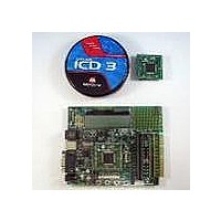
KIT EVAL ICD3 WITH EXPLORER 16
Manufacturer
Microchip Technology
Series
MPLAB® ICD 3r
Type
MCUr
Datasheet
1.DV164037.pdf
(50 pages)
Specifications of DV164037
Contents
2 Boards, ICD3 Debugger
Processor To Be Evaluated
PIC24F, PIC24H, dsPIC33
Data Bus Width
16 bit
Interface Type
RS-232, USB
Operating Supply Voltage
9 V
Silicon Manufacturer
Microchip
Core Architecture
PIC
Core Sub-architecture
PIC24, DsPIC33
Silicon Core Number
PIC24F, DsPIC33F
Silicon Family Name
PIC24FJxxGAxxx, DsPIC33FJxxGPxxx
Lead Free Status / RoHS Status
Lead free / RoHS Compliant
For Use With/related Products
PIC24F, PIC24H, dsPIC33
Lead Free Status / Rohs Status
Lead free / RoHS Compliant
Available stocks
Company
Part Number
Manufacturer
Quantity
Price
Company:

Part Number:
DV164037
Manufacturer:
MICROCHIP
Quantity:
12 000


Explorer 16 Development Board User’s Guide
1.5
DS51589A-page 9
USING THE EXPLORER 16 OUT OF THE BOX
FIGURE 1-1:
Although intended as a development platform, the Explorer 16 board may also be used
directly from the box as a demonstration board for PIC24 and dsPIC33F devices. The
programs discussed in Chapter 3. “Explorer 16 Tutorial Programs” are
preprogrammed into the sample device PIMs (i.e., PIC24ExplDemo.hex for the
PIC24 device and dsPIC33ExplDemo.hex for the dsPIC33F device) and are ready
for immediate use.
To get started with the board:
1. For Explorer 16 boards without a permanently mounted PIC24FJ device: verify
2. For Explorer 16 boards without a permanently mounted PIC24FJ device: verify
3. Verify that the jumper on JP2 is installed (to enable the LEDs).
4. Apply power to the board (9 VDC) at power input J2. For information on accept-
Refer to Chapter 3. “Explorer 16 Tutorial Programs” for details on the demonstration
code operation.
9
8
7
6
5
4
3
that the PIC24FJ128GA010 PIM is correctly installed onto the board. If you want
to use the dsPIC
dsPIC33F PIM in its place. For all PIMs, be certain to align the PIM so the
notched corner marking is oriented in the upper left corner.
that switch S2 is set in the “PIM” position.
For Explorer 16 boards with a permanently mounted PIC24FJ device: verify that
switch S2 is set in the “PIC” position.
able power sources, see Appendix A. “Explorer 16 Development Board
Schematics”.
10
2
EXPLORER 16 DEVELOPMENT BOARD LAYOUT
®
1
device PIM, carefully remove the PIC24 PIM and install the
11
12
13
© 2005 Microchip Technology Inc.
14
15
16
17
18
19
20
Related parts for DV164037
Image
Part Number
Description
Manufacturer
Datasheet
Request
R

Part Number:
Description:
Manufacturer:
Microchip Technology Inc.
Datasheet:
Part Number:
Description:
Manufacturer:
Microchip Technology Inc.
Datasheet:
Part Number:
Description:
Manufacturer:
Microchip Technology Inc.
Datasheet:
Part Number:
Description:
Manufacturer:
Microchip Technology Inc.
Datasheet:
Part Number:
Description:
Manufacturer:
Microchip Technology Inc.
Datasheet:
Part Number:
Description:
Manufacturer:
Microchip Technology Inc.
Datasheet:
Part Number:
Description:
Manufacturer:
Microchip Technology Inc.
Datasheet:
Part Number:
Description:
Manufacturer:
Microchip Technology Inc.
Datasheet: