DV164037 Microchip Technology, DV164037 Datasheet - Page 34
DV164037
Manufacturer Part Number
DV164037
Description
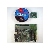
KIT EVAL ICD3 WITH EXPLORER 16
Manufacturer
Microchip Technology
Series
MPLAB® ICD 3r
Type
MCUr
Datasheet
1.DV164037.pdf
(50 pages)
Specifications of DV164037
Contents
2 Boards, ICD3 Debugger
Processor To Be Evaluated
PIC24F, PIC24H, dsPIC33
Data Bus Width
16 bit
Interface Type
RS-232, USB
Operating Supply Voltage
9 V
Silicon Manufacturer
Microchip
Core Architecture
PIC
Core Sub-architecture
PIC24, DsPIC33
Silicon Core Number
PIC24F, DsPIC33F
Silicon Family Name
PIC24FJxxGAxxx, DsPIC33FJxxGPxxx
Lead Free Status / RoHS Status
Lead free / RoHS Compliant
For Use With/related Products
PIC24F, PIC24H, dsPIC33
Lead Free Status / Rohs Status
Lead free / RoHS Compliant
Available stocks
Company
Part Number
Manufacturer
Quantity
Price
Company:

Part Number:
DV164037
Manufacturer:
MICROCHIP
Quantity:
12 000


© 2005 Microchip Technology Inc.
4.2.14
Connector J14 provides the footprint for a 6-pin PICkit 2 programmer interface. This will
provide a third low-cost programming option, besides MPLAB ICD 2 and the JTAG
interface, when PICkit 2 support for larger devices become available in the future.
4.2.15
Connector J13 provides a standard JTAG interface, allowing users to connect to and
program the controller via JTAG.
4.2.16
The Explorer 16 board has been designed with the PICtail™ Plus modular expansion
interface, allowing the board to provide basic generic functionality and still be easily
extendable to new technologies as they become available.
PICtail Plus is based on a 120-pin connection divided into three sections of 30 pins,
30 pins and 56 pins. The two 30-pin connections have parallel functionality; for exam-
ple, pins 1, 3, 5 and 7 have SPI1 functionality on the top 30-pin segment, with similar
SPI2 functionality on the corresponding pins in the middle 30-pin segment.
Each 30-pin section provides connections to all of the serial communications
peripherals, as well as many I/O ports, external interrupts and A/D channels. This pro-
vides enough signals to develop many different expansion interfaces, such as
Ethernet, Zigbee™, IrDA
used in either the top or middle 30-pin sections.
The Explorer 16 board provides footprints for two edge connectors for daughter cards,
one populated (J5, Samtec # MEC1-160-02-S-D-A) and one unpopulated (J6). The
board also has a matching male edge connection (J9), allowing it to be used as an
expansion card itself.
4.2.16.1
The PICtail Plus interface allows two Explorer 16 boards to be connected directly to
each other without any external connector. This provides 1-to-1 connection between
the microcontrollers on the two boards, an interface that works well for many types of
peripherals (I
and UARTs, require cross-wire connections; that is, the TX (or SDO) pin of one
controller must be connected to the RX (or SDI) of the other and vice versa.
The Explorer 16 board uses two 74HCT4053 analog multiplexers to simplify the con-
nections between itself and any daughter boards. U6 and U7 provide active control of
the cross-wire capability on SPI1 and UART1, with a hardware flow control signal
provided by three I/O pins.
The multiplexers are controlled by the state of pins RB12, RB13 and RB14. When a
control pin is high (the default state), the corresponding SPI1 or UART1 pin pairs are
connected to their default pins on the PICtail Plus interface. When a control pin is
asserted low, the corresponding pin pair functions are swapped. Table 4-1 details the
relationship between the control pins and SPI1/UART1 functions on the interface.
PICkit 2 Connector
JTAG Connector
PICtail™ Plus Card Edge Modular Expansion Connectors
CROSSOVER CONNECTIONS FOR SPI AND UART
2
C, PMP, etc.). However, certain serial peripheral modules, such as SPIs
Explorer 16 Development Hardware
®
and so on. The 30-pin PICtail Plus expansion boards can be
DS51589A-page 30
Related parts for DV164037
Image
Part Number
Description
Manufacturer
Datasheet
Request
R

Part Number:
Description:
Manufacturer:
Microchip Technology Inc.
Datasheet:
Part Number:
Description:
Manufacturer:
Microchip Technology Inc.
Datasheet:
Part Number:
Description:
Manufacturer:
Microchip Technology Inc.
Datasheet:
Part Number:
Description:
Manufacturer:
Microchip Technology Inc.
Datasheet:
Part Number:
Description:
Manufacturer:
Microchip Technology Inc.
Datasheet:
Part Number:
Description:
Manufacturer:
Microchip Technology Inc.
Datasheet:
Part Number:
Description:
Manufacturer:
Microchip Technology Inc.
Datasheet:
Part Number:
Description:
Manufacturer:
Microchip Technology Inc.
Datasheet: