DV164037 Microchip Technology, DV164037 Datasheet - Page 33
DV164037
Manufacturer Part Number
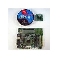
DV164037
Description
KIT EVAL ICD3 WITH EXPLORER 16
Manufacturer
Microchip Technology
Series
MPLAB® ICD 3r
Type
MCUr
Datasheet
1.DV164037.pdf
(50 pages)
Specifications of DV164037
Contents
2 Boards, ICD3 Debugger
Processor To Be Evaluated
PIC24F, PIC24H, dsPIC33
Data Bus Width
16 bit
Interface Type
RS-232, USB
Operating Supply Voltage
9 V
Silicon Manufacturer
Microchip
Core Architecture
PIC
Core Sub-architecture
PIC24, DsPIC33
Silicon Core Number
PIC24F, DsPIC33F
Silicon Family Name
PIC24FJxxGAxxx, DsPIC33FJxxGPxxx
Lead Free Status / RoHS Status
Lead free / RoHS Compliant
For Use With/related Products
PIC24F, PIC24H, dsPIC33
Lead Free Status / Rohs Status
Lead free / RoHS Compliant
Available stocks
Company
Part Number
Manufacturer
Quantity
Price
Company:

Part Number:
DV164037
Manufacturer:
MICROCHIP
Quantity:
12 000


Explorer 16 Development Board User’s Guide
DS51589A-page 29
FIGURE 4-1:
4.2.8
The Explorer 16 also has a footprint and layout support for the Optrex 128 x 64 dot-matrix
graphic LCD (part number F-51320GNB-LW-AB) and associated circuitry. This is the
same display used in Microchip’s MPLAB PM3 programmer.
4.2.9
Five push button switches provide the following functions:
• S1: Active-low MCLR switch to hard reset the processor
• S3: Active-low switch connected to RD6 (user-defined)
• S4: Active-low switch connected to RD13 (user-defined)
• S5: Active-low switch connected to RA7 (user-defined)
• S6: Active-low switch connected to RD7 (user-defined)
Switch S1 has a debounce capacitor, whereas S3 through S6 do not; this allows the
user to investigate debounce techniques. When Idle, the switches are pulled high
(+3.3V). When pressed, they are grounded.
4.2.10
A 10 kΩ potentiometer is connected through a series resistor to AN5. It can be adjusted
from V
4.2.11
Eight red LEDs (D2 through D9) are connected to PORTA of the PIM socket. The
PORTA pins are set high to light the LEDs. These LEDs may be disabled by removing
jumper JP2.
4.2.12
The installed microcontroller has two separate oscillator circuits connected.The main
oscillator uses an 8 MHz crystal (Y3) and functions as the controller’s primary oscillator.
A second circuit, using a 32.768 kHz (watch type) crystal (Y2), functions as the Timer1
oscillator and serves as the source for the RTCC and secondary oscillator.
The PIC18LF4550, at the heart of the USB subsystem, is independently clocked and
has its own 20 MHz crystal (Y1).
4.2.13
A 25LC256 256K (32K x 8) serial EEPROM (U5) is included for nonvolatile firmware
storage. It is also used to demonstrate SPI bus operation.
Cut Traces
Here
DD
to GND to provide an analog input to one of the controller’s A/D channels.
Graphic LCD
Switches
Analog Input (Potentiometer)
LEDs
Oscillator Options
Serial EEPROM
MODIFICATIONS TO R60-R67 FOR LCD CONFIGURATION
(SCALE ENHANCED FOR VISIBILITY)
© 2005 Microchip Technology Inc.
Bridges
Solder
Here
Add
Related parts for DV164037
Image
Part Number
Description
Manufacturer
Datasheet
Request
R

Part Number:
Description:
Manufacturer:
Microchip Technology Inc.
Datasheet:
Part Number:
Description:
Manufacturer:
Microchip Technology Inc.
Datasheet:
Part Number:
Description:
Manufacturer:
Microchip Technology Inc.
Datasheet:
Part Number:
Description:
Manufacturer:
Microchip Technology Inc.
Datasheet:
Part Number:
Description:
Manufacturer:
Microchip Technology Inc.
Datasheet:
Part Number:
Description:
Manufacturer:
Microchip Technology Inc.
Datasheet:
Part Number:
Description:
Manufacturer:
Microchip Technology Inc.
Datasheet:
Part Number:
Description:
Manufacturer:
Microchip Technology Inc.
Datasheet: