MPC8313E-RDB Freescale Semiconductor, MPC8313E-RDB Datasheet - Page 42
MPC8313E-RDB
Manufacturer Part Number
MPC8313E-RDB
Description
BOARD PROCESSOR
Manufacturer
Freescale Semiconductor
Series
PowerQUICC II™ PROr
Type
MCUr
Datasheets
1.MPC8313CZQAFFB.pdf
(100 pages)
2.MPC8313E-RDBB.pdf
(52 pages)
3.MPC8313E-RDBB.pdf
(2 pages)
Specifications of MPC8313E-RDB
Contents
Reference Design Board, Software and Documentation
Termination Type
SMD
Supply Voltage Max
1.05V
Tool / Board Applications
Wired Connectivity-LIN, CAN, Ethernet, USB
Mcu Supported Families
POWERQUICC II PRO
Rohs Compliant
Yes
Filter Terminals
SMD
Silicon Manufacturer
Freescale
Silicon Core Number
MPC83xx
Kit Application Type
Communication & Networking
Application Sub Type
Ethernet
Core Architecture
Power Architecture
Silicon Family Name
PowerQUICC II PRO
For Use With/related Products
MPC8313E
Lead Free Status / RoHS Status
Lead free / RoHS Compliant


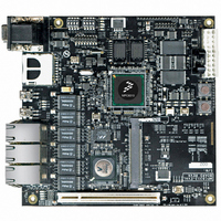
MPC8313E RDB Board Configuration
5.3
The MPC8313E RDB requires a power supply from the ATX power connector. The ATX supply connector
directly provides 12-V, 5-V, and 3.3-V voltages. Core voltage, DDR2 voltage, RGMII voltage, and
PHY-specific voltages are provided by either switching or linear regulated depending on the voltage drop
and current consumption requirement. MPC8313E power-down mode is supported. A regulator that can
be shut down is implemented for this purpose.
The MPC8313E does not require the core supply voltage and IO supply voltages to be applied in any
particular order. However, during the power ramp up, before the power supplies are stable, there may be
an interval when the IO pins are actively driven. After the power is stable, as long as PORESET is asserted,
most IO pins are three-stated. To minimize the time that IO pins are actively driven, apply core voltage
before IO voltage and assert PORESET before the power supplies fully ramp up.
Table 21
42
1 V shutdownable
19-21
22-27
30-31
Bits
Voltage
28
29
1.2 V
1.8 V
2.5 V
3.3 V
1 V
shows the power supply table.
Power Supply
Table 20. Reset Configuration Word High (RCWH) Bit Descriptions (continued)
Reserved
Reserved
TSEC2M
Name
LALE
TLE
VSC7385, 88E1111
PowerQUICC™ MPC8313E Reference Design Board (RDB), Rev. 4
VDD, AVDD1
General IO
Usage
RGMII
VDDC
DDR2
TSEC2 Mode
—
True little endian
Local Bus ALE
signal timing
—
Table 21. Power Supply Usage Summary
Meaning
0.5 A + DDR chip x2pcs
0.2 A + 0.2 A + 0.2 A
000
001
011:Default
101
110
010,100,111
Must be cleared
0: Default
1
0: Default
1
Must be cleared
1.75 A + 0.4 A
Variable
Budget
<10 A
<1 A
MII mode
RMII mode
RGMII mode
RTBI mode
SGMII mode
Reserved
Big-endian mode
True little endian mode
Normal LALE timing
LALE is negated 1/2 lbc_controller_clk earlier.
MIC1510ETB+ regulator (3 A) with tracking
Description
MIC1953EUB+ switching
MIC39100-2.5WS (1 A)
Direct from ATX Power
MIC37302 LDO (3 A)
MIC37302 LDO (3 A)
Solution
Freescale Semiconductor
Related parts for MPC8313E-RDB
Image
Part Number
Description
Manufacturer
Datasheet
Request
R

Part Number:
Description:
Mpc8313e Powerquicc Ii Pro Processor
Manufacturer:
Freescale Semiconductor, Inc
Datasheet:

Part Number:
Description:
BOARD CPU 8313E VER 2.1
Manufacturer:
Freescale Semiconductor
Datasheet:

Part Number:
Description:
BOARD CPU 8313E VER 2.2
Manufacturer:
Freescale Semiconductor
Datasheet:
Part Number:
Description:
Microprocessors - MPU 8313 REV2.2 PB ENC EXT
Manufacturer:
Freescale Semiconductor
Datasheet:
Part Number:
Description:
Microprocessors - MPU 8313 REV2.2 PB W/ENC
Manufacturer:
Freescale Semiconductor
Datasheet:
Part Number:
Description:
Microprocessors - MPU 8313 REV2.2 PB NO EN EXT
Manufacturer:
Freescale Semiconductor
Datasheet:
Part Number:
Description:
Microprocessors - MPU 8313 REV2.2 PB NO ENC
Manufacturer:
Freescale Semiconductor
Datasheet:
Part Number:
Description:
Manufacturer:
Freescale Semiconductor, Inc
Datasheet:
Part Number:
Description:
Manufacturer:
Freescale Semiconductor, Inc
Datasheet:
Part Number:
Description:
Manufacturer:
Freescale Semiconductor, Inc
Datasheet:
Part Number:
Description:
Manufacturer:
Freescale Semiconductor, Inc
Datasheet:
Part Number:
Description:
Manufacturer:
Freescale Semiconductor, Inc
Datasheet:
Part Number:
Description:
Manufacturer:
Freescale Semiconductor, Inc
Datasheet:
Part Number:
Description:
Manufacturer:
Freescale Semiconductor, Inc
Datasheet:
Part Number:
Description:
Manufacturer:
Freescale Semiconductor, Inc
Datasheet: