MPC8313E-RDB Freescale Semiconductor, MPC8313E-RDB Datasheet - Page 48
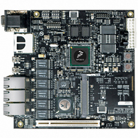
MPC8313E-RDB
Manufacturer Part Number
MPC8313E-RDB
Description
BOARD PROCESSOR
Manufacturer
Freescale Semiconductor
Series
PowerQUICC II™ PROr
Type
MCUr
Datasheets
1.MPC8313CZQAFFB.pdf
(100 pages)
2.MPC8313E-RDBB.pdf
(52 pages)
3.MPC8313E-RDBB.pdf
(2 pages)
Specifications of MPC8313E-RDB
Contents
Reference Design Board, Software and Documentation
Termination Type
SMD
Supply Voltage Max
1.05V
Tool / Board Applications
Wired Connectivity-LIN, CAN, Ethernet, USB
Mcu Supported Families
POWERQUICC II PRO
Rohs Compliant
Yes
Filter Terminals
SMD
Silicon Manufacturer
Freescale
Silicon Core Number
MPC83xx
Kit Application Type
Communication & Networking
Application Sub Type
Ethernet
Core Architecture
Power Architecture
Silicon Family Name
PowerQUICC II PRO
For Use With/related Products
MPC8313E
Lead Free Status / RoHS Status
Lead free / RoHS Compliant


Frequently Asked Questions (FAQs)
8.2
You should set the RDB to use a hardcoded reset configuration and reprogram the flash memory by
debugger (for example, CodeWarrior debugger + USBTAP). To use a hardcoded reset configuration, set
DIP switch S3 as OFF-ON-OFF-OFF (1011). On the other hand, if there is a reset configuration in NAND
Flash or the I
Alternatively, some REVA3 and all later boards have the I
used to reprogram the NOR Flash memory without a debugger. The procedure is as follows:
48
Revision
1. Power off the board and set DIP switch S3 as ON-OFF-ON-ON (0100).
2. Connect the board to Kermit (a UART terminal program; the other terminal program does not
3. Set the baud rate in Kermit as 38400 bps (for a 66 MHz clock-in RDB) or 19200 bps (for a 33
4. Power on the board and you should see the following in Kermit:
5. Go to Kermit → Send and select the u-boot image binary to be written into flash memory.
6. Wait for the file transfer and flash programming until you see
7. Power off the board and set DIP switch S3 back to ON-ON-ON-ON (0000).
8. Power on the board and you should see a running u-boot.
REVA4
REVB
REVC
work at this mode). Kermit can be downloaded from http://kermit.wwarthen.com/Download.htm.
MHz clock-in RDB).
What should I do if the flash (NOR flash) image on the RDB is
accidentally erased?
Hello and welcome to I2C BOOTLOADER
## Ready for binary (kermit) download
2
Fixes the second drawback point of REVA3.
C EEPROM, you may want to use either one as a hard reset configuration source.
• Added GTX_CLK125 sourced from external 125 MHz oscillator.
• Added an optional IEEE 1588 connector (P10).
• Added three more resistor options (R311–R313) to route 3 IEEE 1588 signals that only available in eTSEC1
• Changed S4 to support LB_POR_CFG_BOOT_ECC_DIS.
• Changed SD chip select signal from SPISEL(GPIO31) to GPIO13.
• Added a Marvell 88E1111 PHY. Phy address assigned to 0x3. Use same IRQ3# as L2 Switch.
• Added resistor option for RGMII signals route to either to L2 Switch or Marvell 88E1111 PHY.
• Added SGMII support for eTSEC1 if using the added Marvell 88E1111 PHY. (SGMII for eTSEC2 already
• Added PLL CY23EP05SXC-1 U86 to PHY gerneated 125 MHz clock.
• Changed default TSEC1_GTX_CLK125 clock source to PLL CY23EP05SX-1 instead of external 125 MHZ
• Changed U36 1A linear regulator MIC39100-2.5WS to 3A MIC37302WR for higher 2.5V power consumption
• Changed default DAC to 16-bit SPI controlled MAX5203BEUB+ (U47).
to the IEEE 1588 connector.
supported.)
oscillator.
by additional PHY.
PowerQUICC™ MPC8313E Reference Design Board (RDB), Rev. 4
Table 24. MPC8313E-RBD Revisions
Description
2
C EEPROM bootloader programmed. It can be
success
in the Kermit window.
Freescale Semiconductor
Related parts for MPC8313E-RDB
Image
Part Number
Description
Manufacturer
Datasheet
Request
R

Part Number:
Description:
Mpc8313e Powerquicc Ii Pro Processor
Manufacturer:
Freescale Semiconductor, Inc
Datasheet:

Part Number:
Description:
BOARD CPU 8313E VER 2.1
Manufacturer:
Freescale Semiconductor
Datasheet:

Part Number:
Description:
BOARD CPU 8313E VER 2.2
Manufacturer:
Freescale Semiconductor
Datasheet:
Part Number:
Description:
Microprocessors - MPU 8313 REV2.2 PB ENC EXT
Manufacturer:
Freescale Semiconductor
Datasheet:
Part Number:
Description:
Microprocessors - MPU 8313 REV2.2 PB W/ENC
Manufacturer:
Freescale Semiconductor
Datasheet:
Part Number:
Description:
Microprocessors - MPU 8313 REV2.2 PB NO EN EXT
Manufacturer:
Freescale Semiconductor
Datasheet:
Part Number:
Description:
Microprocessors - MPU 8313 REV2.2 PB NO ENC
Manufacturer:
Freescale Semiconductor
Datasheet:
Part Number:
Description:
Manufacturer:
Freescale Semiconductor, Inc
Datasheet:
Part Number:
Description:
Manufacturer:
Freescale Semiconductor, Inc
Datasheet:
Part Number:
Description:
Manufacturer:
Freescale Semiconductor, Inc
Datasheet:
Part Number:
Description:
Manufacturer:
Freescale Semiconductor, Inc
Datasheet:
Part Number:
Description:
Manufacturer:
Freescale Semiconductor, Inc
Datasheet:
Part Number:
Description:
Manufacturer:
Freescale Semiconductor, Inc
Datasheet:
Part Number:
Description:
Manufacturer:
Freescale Semiconductor, Inc
Datasheet:
Part Number:
Description:
Manufacturer:
Freescale Semiconductor, Inc
Datasheet: