101-0359 Rabbit Semiconductor, 101-0359 Datasheet
101-0359
Specifications of 101-0359


Related parts for 101-0359


101-0359 Summary of contents
Page 1
Rabbit 2000 Microprocessor Development Kit Getting Started Manual 019–0068 • 050515–F ...
Page 2
... Z-World Inc. • All rights reserved. Z-World reserves the right to make changes and improvements to its products without providing notice. Rabbit is a registered trademark of Rabbit Semiconductor. Rabbit 2000 is a trademark of Rabbit Semiconductor. Z-World and Dynamic C are registered trademarks of Z-World Inc. ...
Page 3
Chapter 1. Introduction 1.1 Development Kit Contents....................................................................................................................1 1.2 Development Software .........................................................................................................................2 1.3 How to Use This Manual ......................................................................................................................2 1.3.1 Additional Product Information ....................................................................................................2 1.3.2 Additional Reference Information ................................................................................................2 1.3.3 Using Online Documentation........................................................................................................3 1.4 CE Compliance .....................................................................................................................................4 1.4.1 Spectrum Spreader ........................................................................................................................5 ...
Page 4
Appendix A. Reference Information A.1 Electrical and Mechanical Specifications.......................................................................................... 40 A.2 Header Pinout .................................................................................................................................... 41 A.3 Jumper Configurations ...................................................................................................................... 42 A.4 Use of Rabbit 2000 Parallel Ports ..................................................................................................... 44 Notice to Users Index Schematics Rabbit 2000 ...
Page 5
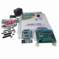
The Rabbit 2000 is a new and powerful microprocessor. Both hardware and software design are easy with the Rabbit. This Development Kit has the essentials that you need to design your own a microprocessor-based system, and includes a com- ...
Page 6
Development Software The BL1810 in the Development Kit uses the Dynamic C development environment for rapid creation and debugging of runtime applications. Dynamic C provides a complete development environment with integrated editor, compiler and source-level debugger. It interfaces directly ...
Page 7
Using Online Documentation We provide the bulk of our user and reference documentation in two electronic formats, HTML and Adobe PDF this for several reasons. We believe that providing all users with our complete library of product ...
Page 8
CE Compliance Equipment is generally divided into two classes. CLASS A Digital equipment meant for light industrial use Less restrictive emissions requirement: less than 40 dB µV (40 dB relative to 1 µV/m) or 300 µV/m ...
Page 9
... When connecting the BL1800 single-board computer to outdoor cables, the customer is responsible for providing CE-approved surge/lightning protection. • Rabbit Semiconductor recommends placing digital I/O or analog cables that are longer in a metal conduit to assist in maintaining CE compliance and to conform to good cable design practices. Rabbit Semiconductor also recommends using properly shielded I/O cables in noisy electromagnetic environments. • ...
Page 10
... Since the BL1800 series of single-board computers is designed to be connected to other devices, good EMC practices should be followed to ensure compliance. CE compliance is ultimately the responsibility of the integrator. Additional information, tips, and technical assistance are available from your authorized Rabbit Semiconductor distributor, and are also available on the Z-World Web site at www.zworld.com. 6 ...
Page 11
D ETAILED Chapter 2 contains detailed instructions for installing the soft- ware on your PC and for connecting the BL1810 to your PC in order to run sample programs. 2.1 Software Installation You will need approximately 200 megabytes of ...
Page 12
Prototyping Board The Prototyping Board included in the Development Kit makes it easy to connect a BL1810 to a power supply and a PC workstation for development. It also provides some basic I/O peripherals (switches and LEDs), as well ...
Page 13
Prototyping Board Features —The power LED lights whenever power is connected to the Prototyping Power LED • Board. —A momentary-contact, normally open switch is connected directly to the Reset Switch • BL1810’s pin. Pressing the switch forces a hardware ...
Page 14
Development Hardware Connections There are three steps to connecting the Prototyping Board for use with Dynamic C and the sample programs: 1. Attach the BL1810 to the Prototyping Board. 2. Connect the programming cable between the BL1810 and the ...
Page 15
Attach BL1810 to Prototyping Board To attach the BL1810 to the Prototyping Board, turn the BL1810 over so that the battery is facing up. Plug the pins from headers J4 and J5 on the bottom side of the BL1810 ...
Page 16
... NOTE: Use only the programming cable that has a red shrink wrap around the RS-232 level converter (Z-World part number 101-0513), which is supplied with the Develop- ment Kit. Other Z-World programming cables might not be voltage-compatible or their connector sizes may be different. ...
Page 17
Connect Power When all other connections have been made, you can connect power to the BL1810. Hook up the connector from the wall transformer to header J1 on the BL1810 as shown in Figure 3. The orientation of this ...
Page 18
Start Dynamic C Once the BL1810 is connected as described in Section 2.3, ing on the Dynamic C icon or by double-clicking on dcrabXXXX.exe in the Dynamic C root directory, where XXXX are version-specific characters If you are using ...
Page 19
... For advanced development topics, refer to the Dynamic C User’s Manual, also in the online documentation set. 2.6.1 Technical Support NOTE: If you purchased your Rabbit 2000 Development Kit through a distributor or through a Rabbit Semiconductor partner, contact the distributor or partner first for technical support. If there are any problems at this point: • Use the Dynamic C Help • ...
Page 20
Rabbit 2000 Development Kit ...
Page 21
A series of sample programs is provided in the Dynamic C The sample programs are listed in Table 1. Table 1. BL1810 Sample Programs The first five sample programs provide a step-by-step introduction to the BL1810 board. Additional sample programs ...
Page 22
Running Sample Program DEMOJR1.C This sample program can be used to illustrate some of the functions of Dynamic C. First, open the file DEMOJR1.C will appear in a window, as shown in Figure 4 below (minus some comments). Use ...
Page 23
The programming cable must be connected to the BL1810. (The colored wire on the programming cable is closest to pin 1 on header J3 on the BL1810, as shown in Figure 3.) The other end of the programming cable ...
Page 24
Editing the Program Click on the box on the task bar. This will set Dynamic C into the edit mode so that Edit you can change the program. Use the with a new name so as not to change the ...
Page 25
Setting break points. The F2 the cursor position if the program has already been compiled. You can set a break point if the program is paused at a break point. You can also set a break point in a ...
Page 26
Other Sample Programs Illustrating Digital I/O —repeatedly flashes LED DS3 (which is controlled by PA2) on the Proto- • DEMOJR2.C typing Board. This sample program also illustrates the use of the Dynamic C to update watch expressions while running. ...
Page 27
Before running the LCD_DEMO.C HD44780 (or an equivalent) controller. —demonstrates a 4-bit interface to an LCD based on the HD44780 (or an • LCD_DEMO.C equivalent) controller. Connect the LCD to Parallel Port A. PA0—LCD DB4 PA1—LCD DB5 PA2—LCD DB6 PA3—LCD ...
Page 28
RS-232 Serial Communication Sample Programs —This program demonstrates hardware flow control by config- • JR_FLOWCONTROL.C uring Serial Port C (PC3/PC2) for CTS/RTS with serial data coming from TxB at 115,200 bps. One character at a time is received and ...
Page 29
RS-485 Serial Communication Sample Program The following sample program illustrates the use of the RS-485 serial drivers. The sample program shows a byte being transmitted, and then the RS-485 transceiver waits for a reply. #define DINBUFSIZE #define DOUTBUFSIZE 15 ...
Page 30
Cooperative Multitasking Cooperative multitasking is a convenient way to perform several different tasks at the same time. An example would be to step a machine through a sequence of steps and at the same time independently carry on a ...
Page 31
S1 main(){ WrPortI(SPCR,NULL,0x84); WrPortI(PADR,&PADRShadow,0xff); vswitch=0; (1) while (1) { BigLoopTop(); // first task flash LED DS4 every second for 200 milliseconds (2) costate { BitWrPortI(PADR,&PADRShadow,0,3); // LED DS4 on (3) waitfor(DelayMs(200)); BitWrPortI(PADR,&PADRShadow,1,3); // LED DS4 off waitfor(DelayMs(800)); (4) ...
Page 32
Place the cursor on this function name The statement at (3) waits for a time delay, in this case 200 ms. The costatement ...
Page 33
Switching Between Program Mode and Run Mode The BL1810 is automatically in Program Mode when the programming cable is attached, and is automatically in Run Mode when no programming cable is attached. See Figure 5. Figure 5. BL1810 Program ...
Page 34
Rabbit 2000 Development Kit ...
Page 35
... To develop and debug programs for the BL1810 (and for all other Z-World and Rabbit Semiconductor hardware), you must install and use Dynamic C. It runs on an IBM-compatible PC and is designed for use with Z-World single-board computers and other devices based on the Rabbit microprocessor. This chapter provides a tour of the major features of Dynamic C with respect to the BL1810 ...
Page 36
Dynamic C has a number of standard features: • Full-feature source and/or assembly-level debugger, no in-circuit emulator required. • Royalty-free TCP/IP stack with source code and most common protocols. • Hundreds of functions in source-code libraries and sample programs: Exceptionally ...
Page 37
Upgrading Dynamic C 4.1.1.1 Patches and Bug Fixes Dynamic C patches that focus on bug fixes are available from time to time. Check the Web site • www.zworld.com/support/ for the latest patches, workarounds, and bug fixes. The default installation ...
Page 38
BL1810 Function Calls 4.2.1 I/O Drivers The BL1810 contains four high-power digital output channels, two D/A converter output channels, and one A/D converter input channel. These I/O channels can be accessed using the functions found in the JRIO.LIB 4.2.1.1 ...
Page 39
BL1810). value is the output value (0 or 1). void digOn(int channel); sets ...
Page 40
Table 2. Typical Analog Output Voltages Corresponding Channel DA0 DA1 0.004 V The output value is set using the following function. void anaOut(int channel, int value); sets the state of an analog output channel. jrioInit must be called first. channel ...
Page 41
Analog Input The analog input channel on the BL1810 (AD0 on header J5) works by varying analog output channel DA0 until its voltage matches the input voltage on AD0. DA0 obviously cannot be used while an input voltage ...
Page 42
Serial Communication Drivers Library files included with Dynamic C provide a full range of serial communications sup- port. The library provides a set of circular-buffer-based serial functions. The RS232.LIB library provides packet-based serial functions where packets can be delim- ...
Page 43
PPENDIX Appendix A provides the specifications and other useful infor- mation for the BL1810. User’s Manual I EFERENCE NFORMATION 39 ...
Page 44
A.1 Electrical and Mechanical Specifications Table A-1. BL1810 Specifications Parameter Microprocessor Flash EPROM SRAM Backup Battery Digital Inputs Digital Outputs Configurable I/O Analog Inputs Analog Outputs Serial Ports Serial Rate Connectors Real-Time Clock Timers Watchdog/Supervisor Power Operating Temperature Humidity Board ...
Page 45
A.2 Header Pinout Figure A-1. Pinout for BL1810 Headers J4 and J5 User’s Manual 41 ...
Page 46
A.3 Jumper Configurations Figure A-2 shows the header and jumper locations used to configure the various BL1810 options. Figure A-2. Location of BL1810 Configurable Positions 42 Rabbit 2000 Development Kit ...
Page 47
Table A-2 lists the configuration options. 0 Ω surface mount resistors are used for all the header positions. Table A-2. BL1810 Jumper Configurations Header Description JP1 SRAM Size JP2 Flash Memory Size JP3 Flash Memory Bank Select — HV3 Sinking/Sourcing ...
Page 48
A.4 Use of Rabbit 2000 Parallel Ports Figure A-3 shows the use of the Rabbit 2000 parallel ports. The BL1810 BL1810 has 24 general-purpose digital inputs/outputs available on headers J4 and J5—14 are bidirec- tional, six are inputs only, and ...
Page 49
... All Rabbit Semiconductor products are 100 percent functionally tested. Additional testing may include visual quality control inspections or mechanical defects analyzer inspections. Specifications are based on characterization of tested sample units rather than testing over temperature and voltage of each unit ...
Page 50
Rabbit 2000 Development Kit ...
Page 51
A additional information online documentation .......... 3 references ............................ 2 B BL1810 electrical specifications ..... language ............................ 31 CE compliance ........................ 4 design guidelines ................. 5 D Development Kit ..................... 1 Dynamic C ........................ 2, 31 standard ...
Page 52
Rabbit 2000 Development Kit ...
Page 53
BL1800 Schematic www.rabbitsemiconductor.com/documentation/schemat/090-0092.pdf 090-0088 Prototyping Board Schematic www.rabbitsemiconductor.com/documentation/schemat/090-0088.pdf 090-0128 Programming Cable Schematic www.rabbitsemiconductor.com/documentation/schemat/090-0128.pdf The schematics included with the printed manual were the latest revisions available at the time the manual was last revised. The online versions of the manual ...
Page 54
...