CY8CKIT-020 Cypress Semiconductor Corp, CY8CKIT-020 Datasheet - Page 67
CY8CKIT-020
Manufacturer Part Number
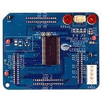
CY8CKIT-020
Description
KIT PSOC CY8C28 FAMILY PROCESSOR
Manufacturer
Cypress Semiconductor Corp
Series
PSoC®r
Type
MCUr
Specifications of CY8CKIT-020
Contents
Board, Software and Documentation
Silicon Manufacturer
Cypress
Core Architecture
PSoC
Features
Programmable System-on-chip Design Methodology And Architecture
Kit Contents
PSoC CY8C28 Module, Doc, CD
Silicon Core Number
CY8C28
Silicon Family Name
PSoC
Rohs Compliant
Yes
Lead Free Status / RoHS Status
Lead free / RoHS Compliant
For Use With/related Products
CY8C28 Family
Lead Free Status / Rohs Status
Supplier Unconfirmed
Other names
428-3036


B.1
B.2
B.3
CY8CKIT-020 PSoC Development Kit Guide, Doc. # 001-56971 Rev. **
Appendix B. MiniProg3
MiniProg3 LEDs
MiniProg3 provides five indicator LEDs:
■
■
■
■
■
Programming in Power Cycle Mode
You should not perform power cycle mode programming with PSoC Programmer on the
CY8CKIT-001. This is due to the way the CY8C38 family module is designed. VTARG of the
MiniProg3 is wired exclusively to VDDIO1 of the chip on the module. In order for power cycle pro-
gramming to work, VTARG would need to be wired to VDDD.
Interface Pin Assignment Table
1
2
3
4
5
Notes:
5-Pin # *
Upper Left - Busy: A red LED that lights when an operation (such as programming or debug) is in
progress.
Lower Left - Status: A green LED that lights when the device is enumerated on the USB bus and
flashes when the MiniProg3 receives USB traffic.
Upper Right - Target Power: A red LED that lights to indicate that the MiniProg3 is supplying
power to the target connectors. Note that it does not light when target power is detected but not
being supplied by MiniProg3.
Lower Right - Aux: A yellow LED reserved for future use.
Middle - No Label: A yellow LED that indicates the configuration state of the device. It flashes
briefly during the initial configuration of the device. If this LED lights solid, a configuration error
has occurred and MiniProg3 must be disconnected from the USB port and reconnected.
1
3,5,7,9
10
4
2
6
8
* The 5- and 10-pin connectors are NOT connected together on the I/O pins
** JTAG is supported only on the 10-pin connector
*** Future upgrades may be possible to support these modes
10-Pin # *
Vtarg
GND
TRST
TCK
TMS
TDO
TDI
JTAG **
Vtarg
GND
SCK
SDIO
SWD
Vtarg
GND
SWO
SWV
Vtarg
GND
XRES
SCLK
SDAT
ISSP
Vtarg
GND
INT
SCLK
SDAT
I2C
67
Related parts for CY8CKIT-020
Image
Part Number
Description
Manufacturer
Datasheet
Request
R

Part Number:
Description:
KIT DEV FOR PSOC3/5
Manufacturer:
Cypress Semiconductor Corp
Datasheet:

Part Number:
Description:
PSoC1/3/5 Development Kit
Manufacturer:
Cypress Semiconductor Corp
Datasheet:

Part Number:
Description:
KIT DEV PSOC PROC MODULE CY8C38
Manufacturer:
Cypress Semiconductor Corp

Part Number:
Description:
KIT DEV PSOC PROC MODULE CY8C29
Manufacturer:
Cypress Semiconductor Corp

Part Number:
Description:
KIT DEV PSOC ANALOG VOLTMETER
Manufacturer:
Cypress Semiconductor Corp
Datasheet:

Part Number:
Description:
KIT DEV PSOC5 FIRST TOUCH
Manufacturer:
Cypress Semiconductor Corp
Datasheet:

Part Number:
Description:
KIT DEV PSOC3 FIRSTTOUCH STARTER
Manufacturer:
Cypress Semiconductor Corp
Datasheet:
Part Number:
Description:
KIT DEV PROC MODULE PSOC5
Manufacturer:
Cypress Semiconductor Corp
Datasheet:

Part Number:
Description:
KIT PSOC MINIPROG3 PROGRAM DEBUG
Manufacturer:
Cypress Semiconductor Corp
Datasheet:

Part Number:
Description:
DEV KIT PSOC 5 CY8C55
Manufacturer:
Cypress Semiconductor Corp
Datasheet:

Part Number:
Description:
KIT EVAL POWERLINE HIGH VOLT
Manufacturer:
Cypress Semiconductor Corp
Datasheet:

Part Number:
Description:
KIT PSOC FIRST TOUCH
Manufacturer:
Cypress Semiconductor Corp
Datasheet:

Part Number:
Description:
EVAL KIT WORLDTOUR2
Manufacturer:
Cypress Semiconductor Corp
Datasheet:

Part Number:
Description:
KIT UNIVERSAL CAPSENSE CTRLR
Manufacturer:
Cypress Semiconductor Corp
Datasheet: