MC56F8006DEMO Freescale Semiconductor, MC56F8006DEMO Datasheet - Page 67
MC56F8006DEMO
Manufacturer Part Number
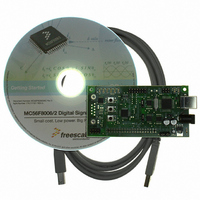
MC56F8006DEMO
Description
DEMO BOARD FOR MC56F8006
Manufacturer
Freescale Semiconductor
Type
DSPr
Datasheets
1.MC56F8006DEMO.pdf
(13 pages)
2.MC56F8006DEMO.pdf
(8 pages)
3.MC56F8006DEMO.pdf
(2 pages)
4.MC56F8006DEMO.pdf
(100 pages)
Specifications of MC56F8006DEMO
Contents
Board
Processor To Be Evaluated
MC56F8006
Interface Type
RS-232, USB
Operating Supply Voltage
3.3 V
Silicon Manufacturer
Freescale
Core Architecture
56800/E
Core Sub-architecture
56800/E
Silicon Core Number
MC56F
Silicon Family Name
MC56F80xx
Rohs Compliant
Yes
For Use With/related Products
MC56F8006
Lead Free Status / RoHS Status
Lead free / RoHS Compliant


9
9.1
An estimation of the chip junction temperature, T
where:
The junction-to-ambient thermal resistance is an industry-standard value that provides a quick and easy estimation of thermal
performance. Unfortunately, there are two values in common usage: the value determined on a single-layer board and the value
obtained on a board with two planes. For packages such as the PBGA, these values can be different by a factor of two. Which
value is closer to the application depends on the power dissipated by other components on the board. The value obtained on a
single layer board is appropriate for the tightly packed printed circuit board. The value obtained on the board with the internal
planes is usually appropriate if the board has low-power dissipation and the components are well separated.
When a heat sink is used, the thermal resistance is expressed as the sum of a junction-to-case thermal resistance and a
case-to-ambient thermal resistance:
where:
R
resistance, R
the mounting arrangement on printed circuit board, or change the thermal dissipation on the printed circuit board surrounding
the device.
To determine the junction temperature of the device in the application when heat sinks are not used, the thermal characterization
parameter (
the package case using the following equation:
where:
The thermal characterization parameter is measured per JESD51–2 specification using a 40-gauge type T thermocouple epoxied
to the top center of the package case. The thermocouple should be positioned so that the thermocouple junction rests on the
package. A small amount of epoxy is placed over the thermocouple junction and over about 1 mm of wire extending from the
Freescale Semiconductor
JC
is device related and cannot be adjusted. You control the thermal environment to change the case to ambient thermal
Design Considerations
Thermal Design Considerations
JT
CA
) can be used to determine the junction temperature with a measurement of the temperature at the top center of
. For instance, you can change the size of the heat sink, the air flow around the device, the interface material,
R
R
R
CA
JA
JC
MC56F8006/MC56F8002 Digital Signal Controller, Rev. 3
P
T
R
JT
T
D
P
T
A
J
D
=
=
=
= Thermocouple temperature on top of package (
=
=
Package junction-to-ambient thermal resistance (°C/W)
=
= Junction-to-ambient thermal resistance (
=
Package case-to-ambient thermal resistance (°C/W)
Package junction-to-case thermal resistance (°C/W)
T
T
R
Thermal characterization parameter (
Ambient temperature for the package (
J
J
J
, can be obtained from the equation:
= T
Power dissipation in the package (W)
JA
= T
Power dissipation in package (W)
A
= R
T
+ (R
+ (
JC
JT
J
+ R
x P
x P
CA
D
D
)
)
o
o
C/W)
o
C/W)
C)
o
C)
Design Considerations
Eqn. 3
Eqn. 4
Eqn. 5
67
Related parts for MC56F8006DEMO
Image
Part Number
Description
Manufacturer
Datasheet
Request
R

Part Number:
Description:
Manufacturer:
Freescale Semiconductor, Inc
Datasheet:
Part Number:
Description:
Manufacturer:
Freescale Semiconductor, Inc
Datasheet:
Part Number:
Description:
Manufacturer:
Freescale Semiconductor, Inc
Datasheet:
Part Number:
Description:
Manufacturer:
Freescale Semiconductor, Inc
Datasheet:
Part Number:
Description:
Manufacturer:
Freescale Semiconductor, Inc
Datasheet:
Part Number:
Description:
Manufacturer:
Freescale Semiconductor, Inc
Datasheet:
Part Number:
Description:
Manufacturer:
Freescale Semiconductor, Inc
Datasheet:
Part Number:
Description:
Manufacturer:
Freescale Semiconductor, Inc
Datasheet:
Part Number:
Description:
Manufacturer:
Freescale Semiconductor, Inc
Datasheet:
Part Number:
Description:
Manufacturer:
Freescale Semiconductor, Inc
Datasheet:
Part Number:
Description:
Manufacturer:
Freescale Semiconductor, Inc
Datasheet:
Part Number:
Description:
Manufacturer:
Freescale Semiconductor, Inc
Datasheet:
Part Number:
Description:
Manufacturer:
Freescale Semiconductor, Inc
Datasheet:
Part Number:
Description:
Manufacturer:
Freescale Semiconductor, Inc
Datasheet:
Part Number:
Description:
Manufacturer:
Freescale Semiconductor, Inc
Datasheet: