DEMO56F8014-EE Freescale Semiconductor, DEMO56F8014-EE Datasheet - Page 77
DEMO56F8014-EE
Manufacturer Part Number
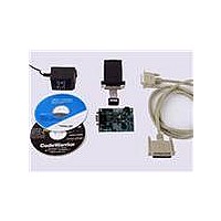
DEMO56F8014-EE
Description
BOARD DEMO FOR 56F8014
Manufacturer
Freescale Semiconductor
Type
MCUr
Datasheets
1.CWH-UTP-ONCE-HE.pdf
(2 pages)
2.APMOTOR56F8000E.pdf
(124 pages)
3.DEMO56F8013-EE.pdf
(2 pages)
Specifications of DEMO56F8014-EE
Contents
*
Processor To Be Evaluated
MC56F8014
Data Bus Width
16 bit
Interface Type
RS-232
For Use With/related Products
56F8014
For Use With
APMOTOR56F8000E - KIT DEMO MOTOR CTRL SYSTEM
Lead Free Status / RoHS Status
Lead free / RoHS Compliant


6.3.10.3
This field represents the lower 16 address bits of the “hard coded” I/O short address.
6.4 Clock Generation Overview
The SIM uses master clocks, 2X system clock at a maximum of 64 MHz, from the OCCS module to
produce the peripheral and system (core and memory) clocks at a maximum of 32 MHz. It divides the
master clock by two and gates it with appropriate power mode and clock gating controls. The high speed
peripheral clock input from OCCS operates at three times the system clock for PWM and Quad Timer
module at a maximum of 96 MHz.
The OCCS configuration controls the operating frequency of the SIM’s master clocks. In the OCCS, either
an external clock or the relaxation oscillator can be selected as the master clock source (MSTR_OSC).
When selected, the relaxation oscillator can be operated at full speed (8 MHz), standby speed (200 kHz),
or powered down. An 8 MHz clock can be multiplied to 192 MHz using the PLL and postscaled to provide
a variety of high speed clock rates. Either the postscaled PLL output or the input clock of the PLL signal
can be selected to produce the master clocks to the SIM. When the PLL is not selected, the high speed
peripheral clock is disabled and the 2x system clock is the input clock from either the internal relaxation
oscillator or from an external clock source.
In combination with the OCCS module, the SIM provides power modes (see
(SIM_PCE register, CLK_DIS, ONCE_EBL), and clock rate controls (TCR, PCR) to provide flexible
control of clocking and power utilization. The SIM’s clock enable controls can be used to disable
individual clocks when not needed. The clock rate controls enable the high speed clocking option for the
Timer channels and PWM but require the PLL to be on and selected. Refer to the 56F801X Peripheral
Reference Manual for further details.
6.5 Power-Down Modes
The 56F8014 operates in one of five Power-Down modes, as shown in
Freescale Semiconductor
Run
Base + $E
RESET
Write
Read
Mode
Figure 6-14 I/O Short Address Location Low Register (SIM_IOSALO)
Input/Output Short Address Location (ISAL[21:6])—Bit 15–0
15
1
Core and memory
clocks disabled
14
Table 6-3 Clock Operation in Power-Down Modes
1
Core Clocks
13
1
12
1
56F8014 Technical Data, Rev. 11
11
1
Peripheral clocks
enabled
Peripheral Clocks
10
1
9
1
8
1
ISAL[21:6]
Device is fully functional
7
1
6
1
5
1
Table 6-3
Description
4
1
Section
.
3
1
Clock Generation Overview
6.5), clock enables
2
1
1
1
0
1
77
Related parts for DEMO56F8014-EE
Image
Part Number
Description
Manufacturer
Datasheet
Request
R

Part Number:
Description:
Manufacturer:
Freescale Semiconductor, Inc
Datasheet:
Part Number:
Description:
Manufacturer:
Freescale Semiconductor, Inc
Datasheet:
Part Number:
Description:
Manufacturer:
Freescale Semiconductor, Inc
Datasheet:
Part Number:
Description:
Manufacturer:
Freescale Semiconductor, Inc
Datasheet:
Part Number:
Description:
Manufacturer:
Freescale Semiconductor, Inc
Datasheet:
Part Number:
Description:
Manufacturer:
Freescale Semiconductor, Inc
Datasheet:
Part Number:
Description:
Manufacturer:
Freescale Semiconductor, Inc
Datasheet:
Part Number:
Description:
Manufacturer:
Freescale Semiconductor, Inc
Datasheet:
Part Number:
Description:
Manufacturer:
Freescale Semiconductor, Inc
Datasheet:
Part Number:
Description:
Manufacturer:
Freescale Semiconductor, Inc
Datasheet:
Part Number:
Description:
Manufacturer:
Freescale Semiconductor, Inc
Datasheet:
Part Number:
Description:
Manufacturer:
Freescale Semiconductor, Inc
Datasheet:
Part Number:
Description:
Manufacturer:
Freescale Semiconductor, Inc
Datasheet:
Part Number:
Description:
Manufacturer:
Freescale Semiconductor, Inc
Datasheet:
Part Number:
Description:
Manufacturer:
Freescale Semiconductor, Inc
Datasheet: