DK-SI-4SGX230N Altera, DK-SI-4SGX230N Datasheet - Page 21
DK-SI-4SGX230N
Manufacturer Part Number
DK-SI-4SGX230N
Description
KIT DEV STRATIX IV 4SGX230N/C2
Manufacturer
Altera
Series
Stratix® IV GXr
Type
FPGAr
Datasheet
1.DK-SI-4SGX230N.pdf
(30 pages)
Specifications of DK-SI-4SGX230N
Contents
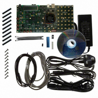
Board, Cables, CD, Power Supply
Silicon Manufacturer
Altera
Core Architecture
FPGA
Core Sub-architecture
Stratix
Silicon Core Number
EP4S
Silicon Family Name
Stratix IV GX
Rohs Compliant
Yes
For Use With/related Products
EP4SGX230
Lead Free Status / RoHS Status
Lead free / RoHS Compliant
Other names
544-2592
DK-SI-4SGX230N/C2
DK-SI-4SGX230N/C2
Available stocks
Company
Part Number
Manufacturer
Quantity
Price


Chapter 6: Stratix IV GX Transceiver Signal Integrity Demonstration
Running the Demonstration Application and Test Designs
© February 2009 Altera Corporation
You can also observe the power and temperature values on the LCD. For more
information, refer to
The power values shown for the VCCA_L/R and the VCCH_GXB assumes that the
jumper settings are set to 3.0 V and 1.4 V, respectively. Click the Help button to see the
required jumper settings.
Channel Reconfig Tab
This tab is only available when signal_integrity_demo3.sof is loaded. You can
dynamically select the input reference clock from the socket clock input or an external
SMA clock input (J19 and J20). To receive the input clock from the external SMA, turn
on switch to SMA clock.
The serial data rate of each transceiver channel can be 16 times or 20 times the clock
rate. The Change Data Rate controls configure each transceiver block with one of the
following data rates:
5 Gbps—Configures the transceiver channel to run at 16 times the input reference
clock. If input reference clock is 312.5 MHz, the transceiver runs at 5 Gbps.
6.25 Gbps—Configures the transceiver channel to run at 20 times the input reference
clock. If input reference clock is 312.5 MHz, the transceiver runs at 6.25 Gbps.
Reverse serial 5G (Post CDR)—Configures the transceiver channel in reverse serial
loop back mode. In this configuration, the output of the RX CDR that is configured to
track serial data input at 16 times the input reference clock is looped to the transmitter
serializer. The serializer is clocked by the recovered clock generated by the RX CDR.
Data checkers are not available for this option.
Reverse serial 6.25G (Post CDR)—Configures the transceiver channel in reverse
serial loop back mode. In this configuration, the output of the RX CDR that is
configured to track serial data input at 20 times the input reference clock is looped to
the transmitter serializer. The serializer is clocked by the recovered clock generated by
the RX CDR. Data checkers are not available for this option.
Reverse serial (Pre CDR)—Configures the transceiver channel in reverse serial (Pre
CDR) mode. The received serial data input is looped to the transmit buffer before it
passes through the RX CDR. Data checkers are not available for this option.
EyeQ Tab
This tab is only available when signal_integrity_demo3.sof is loaded. The options set
the phase step to move the sampling point of the recovered data. For more
information about this feature, refer to “EyeQ” in the
Reconfiguration
The following EyeQ features can be used in channels configured up to 6 Gbps:
Manual—Sets the phase step from 0 to 31. Once the GUI and the hardware computes
3*10E12 bits, the GUI displays the bit error rate (BER) for the phase step, plots the
value, and records the BER information for each phase step in a .csv format. The
block<block number>stats.csv file is saved in the same folder from which the
application is launched.
Automatic—Automatically sequences through the phase steps 0-31, plots the value,
and records the BER information for each phase step in a .csv format.
chapter in volume 2 of the Stratix IV Device Handbook.
“LCD Information” on page
Transceiver Signal Integrity Development Kit, Stratix IV GX Edition User Guide
6–2.
Stratix IV Dynamic
6–7
Related parts for DK-SI-4SGX230N
Image
Part Number
Description
Manufacturer
Datasheet
Request
R

Part Number:
Description:
SI KIT W/SII GX EP2SGX90N
Manufacturer:
Altera
Datasheet:

Part Number:
Description:
KIT DEV STRATIX IV TRANSCEIVER
Manufacturer:
Altera
Datasheet:

Part Number:
Description:
KIT DEV STRATIX V FPGA 5SGXEA7
Manufacturer:
Altera
Datasheet:

Part Number:
Description:
Programmable Logic IC Development Tools FPGA Starter Kit For Stratix V 5SGXEA7
Manufacturer:
Altera Corporation
Part Number:
Description:
Programmable Logic IC Development Tools FPGA Starter Kit For Stratix V 5SGTMC7
Manufacturer:
Altera Corporation
Part Number:
Description:
Programmable Logic IC Development Tools FPGA Starter Kit For Stratix V 5SGTMC7 ES
Manufacturer:
Altera Corporation

Part Number:
Description:
CYCLONE II STARTER KIT EP2C20N
Manufacturer:
Altera
Datasheet:
Part Number:
Description:
CPLD, EP610 Family, ECMOS Process, 300 Gates, 16 Macro Cells, 16 Reg., 16 User I/Os, 5V Supply, 35 Speed Grade, 24DIP
Manufacturer:
Altera Corporation
Datasheet:
Part Number:
Description:
CPLD, EP610 Family, ECMOS Process, 300 Gates, 16 Macro Cells, 16 Reg., 16 User I/Os, 5V Supply, 15 Speed Grade, 24DIP
Manufacturer:
Altera Corporation
Datasheet:
Part Number:
Description:
Manufacturer:
Altera Corporation
Datasheet:
Part Number:
Description:
CPLD, EP610 Family, ECMOS Process, 300 Gates, 16 Macro Cells, 16 Reg., 16 User I/Os, 5V Supply, 30 Speed Grade, 24DIP
Manufacturer:
Altera Corporation
Datasheet:
Part Number:
Description:
High-performance, low-power erasable programmable logic devices with 8 macrocells, 10ns
Manufacturer:
Altera Corporation
Datasheet:
Part Number:
Description:
High-performance, low-power erasable programmable logic devices with 8 macrocells, 7ns
Manufacturer:
Altera Corporation
Datasheet: