8.12.00 J-LINK ARM-PRO Segger Microcontroller Systems, 8.12.00 J-LINK ARM-PRO Datasheet - Page 118
8.12.00 J-LINK ARM-PRO
Manufacturer Part Number
8.12.00 J-LINK ARM-PRO
Description
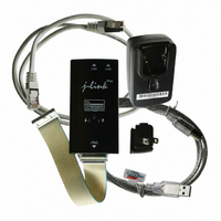
JTAG EMULATOR USB ETHERNET ARM
Manufacturer
Segger Microcontroller Systems
Type
Emulatorr
Specifications of 8.12.00 J-LINK ARM-PRO
Contents
Emulation Module
For Use With/related Products
ARM7, ARM9, ARM11, Cortex
Lead Free Status / RoHS Status
Lead free / RoHS Compliant
Other names
8.12.00 J-LINK ARM-PRO
899-1007
899-1007


118
5.8
5.8.1
5.8.1.1 Type 0: Hardware, halt after reset (normal)
5.8.1.2 Type 1: Hardware, halt with BP@0
5.8.1.3 Type 2: Software, for Analog Devices ADuC7xxx MCUs
J-Link / J-Trace (UM08001)
J-Link / J-Trace supports different reset strategies. This is necessary because there is
no single way of resetting and halting an ARM core before it starts to execute instruc-
tions. For example reset strategies which use the reset pin can not succeed on tar-
gets where the reset pin of the CPU is not connected to the reset pin of the JTAG
connector. Reset strategy 0 is always the recommended one because it has been
adapted to work on every target even if the reset pin (Pin 15) is not connected.
What is the problem if the core executes some instructions after RESET?
The instructions executed can cause various problems. Some cores can be completely
"confused", which means they can not be switched into debug mode (CPU can not be
halted). In other cases, the CPU may already have initialized some hardware compo-
nents, causing unexpected interrupts or worse, the hardware may have been initial-
ized with illegal values. In some of these cases, such as illegal PLL settings, the CPU
may be operated beyond specification, possibly locking the CPU.
The hardware reset pin is used to reset the CPU. After reset release, J-Link continu-
ously tries to halt the CPU. This typically halts the CPU shortly after reset release;
the CPU can in most systems execute some instructions before it is halted. The num-
ber of instructions executed depends primarily on the JTAG speed: the higher the
JTAG speed, the faster the CPU can be halted.
Some CPUs can actually be halted before executing any instruction, because the start
of the CPU is delayed after reset release. If a pause has been specified, J-Link waits
for the specified time before trying to halt the CPU. This can be useful if a bootloader
which resides in flash or ROM needs to be started after reset.
This reset strategy is typically used if nRESET and nTRST are coupled. If nRESET and
nTRST are coupled, either on the board or the CPU itself, reset clears the breakpoint,
which means that the CPU can not be stopped after reset with the BP@0 reset strat-
egy.
The hardware reset pin is used to reset the CPU. Before doing so, the ICE breaker is
programmed to halt program execution at address 0; effectively, a breakpoint is set
at address 0. If this strategy works, the CPU is actually halted before executing a sin-
gle instruction.
This reset strategy does not work on all systems for two reasons:
•
•
This reset strategy is a software strategy. The CPU is halted and performs a sequence
which causes a peripheral reset. The following sequence is executed:
•
•
•
•
This sequence performs a reset of CPU and peripherals and halts the CPU before exe-
cuting instructions of the user program. It is the recommended reset sequence for
Analog Devices ADuC7xxx MCUs and works with these chips only.
Reset strategies
If nRESET and nTRST are coupled, either on the board or the CPU itself, reset
clears the breakpoint, which means the CPU is not stopped after reset.
Some MCUs contain a bootloader program (sometimes called kernel), which
needs to be executed to enable JTAG access.
The CPU is halted
A software reset sequence is downloaded to RAM
A breakpoint at address 0 is set
The software reset sequence is executed.
Strategies for ARM 7/9 devices
CHAPTER 5
© 2004-2011 SEGGER Microcontroller GmbH & Co. KG
Working with J-Link and J-Trace
Related parts for 8.12.00 J-LINK ARM-PRO
Image
Part Number
Description
Manufacturer
Datasheet
Request
R

Part Number:
Description:
CONNECTOR JTAG-ARM ISOLATION
Manufacturer:
Segger Microcontroller Systems
Datasheet:

Part Number:
Description:
ADAPTER ARM TARGET 14PIN RIBBON
Manufacturer:
Segger Microcontroller Systems
Datasheet:

Part Number:
Description:
JTAG EMULATOR FOR ARM CORES
Manufacturer:
Segger Microcontroller Systems
Datasheet:

Part Number:
Description:
JTAG EMULATOR FOR ARM CORES
Manufacturer:
Segger Microcontroller Systems
Datasheet:

Part Number:
Description:
PROGRAMMING TOOL FOR MCU
Manufacturer:
Segger Microcontroller Systems
Datasheet:

Part Number:
Description:
PROGRAMMING TOOL FOR ST7 MCU
Manufacturer:
Segger Microcontroller Systems
Datasheet:

Part Number:
Description:
PROGRAMMING TOOL FOR STM8
Manufacturer:
Segger Microcontroller Systems
Datasheet:

Part Number:
Description:
PROGRAMMER JTAG FOR ARM CORES
Manufacturer:
Segger Microcontroller Systems
Datasheet:

Part Number:
Description:
JTAG EMULATOR ARM7/ARM9 ETM
Manufacturer:
Segger Microcontroller Systems
Datasheet:

Part Number:
Description:
EMULATOR JTAG/SWD CORTEX M3
Manufacturer:
Segger Microcontroller Systems
Datasheet: