RDK-160 Power Integrations, RDK-160 Datasheet - Page 10
RDK-160
Manufacturer Part Number
RDK-160
Description
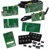
KIT REF DESIGN LINKSWITCH 2
Manufacturer
Power Integrations
Series
LinkSwitch-IIr
Type
MOSFET & Power Driverr
Datasheet
1.LNK603DG.pdf
(18 pages)
Specifications of RDK-160
Mfg Application Notes
LinkSwitch-II Family, Appl Note AN-44
Design Resources
RDR-157, 2.78W USB Charger Using LNK613DG RDR-158, 5W Charger Using LNK616PG RDR-159, 2.4W Charger Using LNK603DG
Main Purpose
AC/DC, Primary Side
Outputs And Type
1, Isolated
Voltage - Input
85 ~ 265VAC
Regulator Topology
Flyback
Board Type
Bare (Unpopulated) and Fully Populated
Utilized Ic / Part
LNK603, LNK604, LNK605, LNK606, LNK613, LNK614, LNK615, LNK616
Product
Power Management Modules
Lead Free Status / RoHS Status
Lead free by exemption / RoHS Compliant
For Use With/related Products
LNK60x, LNK61x
Other names
596-1235


Rev. F 01/10
Output
ON-State
Resistance
OFF-State
Leakage
Breakdown
Voltage
DRAIN Supply
Voltage
Auto-Restart
ON-Time
Auto-Restart
OFF-Time
Open-Loop
FEEDBACK Pin
Current Threshold
Open-Loop
ON-Time
NOTES:
1. Auto-restart ON-time is a function of switching frequency programmed by t
2. The current limit threshold is compensated to cancel the effect of current limit delay. As a result the output current stays constant
3. I
4. When the duty-cycle exceeds DC
5. This parameter is derived from characterization.
6. Mechanical stress induced during the assembly may cause shift in this parameter. This shift has no impact on the ability of
7. The switching frequency is programmable between 60 kHz and 85 kHz.
10
across the input line range.
typical specification under worst case application conditions (rectified 265 VAC) for no-load consumption calculations.
LinkSwitch-II to meet ±10% in mass production given the design follows recommendation in AN-44 and good manufacturing practice
DSS1
LNK603-606/613-616
Parameter
is the worst case OFF state leakage specification at 80% of BV
Symbol
R
BV
t
t
I
I
AR-OFF
AR-ON
DSS1
DSS2
DS(ON)
I
OL
DSS
MAX
the LinkSwitch-II operates in on-time extension mode.
SOURCE = 0 V; T
t
I
I
I
I
ON
D
D
D
D
LNK6X3
LNK6X4
LNK6X5
LNK6X6
(Unless Otherwise Specified)
= 50 mA
= 50 mA
= 62 mA
= 82 mA
× I
V
V
DS
T
DS
FB
J
= 560 V See Figure 20
= 125 °C See Note 3
= 375 V See Figure 20
= 2 mA-ms, f
See Notes 1, 5
See Figure 20
Conditions
See Note 5
See Note 5
T
T
J
J
V
= 50 °C
= 25 °C
FB
= 0
J
= 0 to 100 °C
OSC
T
T
T
T
T
T
T
T
J
J
J
J
J
J
J
J
= 12 kHz
= 100 °C
= 100 °C
= 100 °C
= 100 °C
DSS
= 25 °C
= 25 °C
= 25 °C
= 25 °C
and maximum operating junction temperature. I
on
x I
FB
and minimum frequency in CC mode.
Min
700
50
-120
Typ
450
9.6
1.2
24
36
24
36
16
24
14
15
90
Max
28
42
28
42
19
28
11
17
50
2
www.powerint.com
DSS2
Units
mA
ms
mA
ms
W
V
V
s
is a
Related parts for RDK-160
Image
Part Number
Description
Manufacturer
Datasheet
Request
R

Part Number:
Description:
KIT REF DESIGN FOR LNK457D
Manufacturer:
Power Integrations
Datasheet:

Part Number:
Description:
REFERENCE DESIGN LINKSWITCH-PH
Manufacturer:
Power Integrations
Datasheet:

Part Number:
Description:
KIT REF DESIGN FOR LNK403EG
Manufacturer:
Power Integrations
Datasheet:

Part Number:
Description:
KIT REF DESIGN FOR LNK406EG
Manufacturer:
Power Integrations
Datasheet:

Part Number:
Description:
KIT REF DESIGN LINKSWITCH-CV
Manufacturer:
Power Integrations
Datasheet:

Part Number:
Description:
Specifications: Family: Eval Boards - DC/DC & AC/DC (Off-Line) SMPS ; Series: HiperLCS™ ; Main Purpose: DC/DC, Step Down ; Outputs and Type: 1, Isolated ; Power - Output: 150W ; Voltage - Output: 24V ; Current - Output: 6.25A ; Voltage - Input:
Manufacturer:
Power Integrations, Inc.
Datasheet:

Part Number:
Description:
KIT DESIGN REF TINYSWITCH-III
Manufacturer:
Power Integrations
Datasheet:

Part Number:
Description:
KIT DESIGN REF LINKSWITCH LP
Manufacturer:
Power Integrations
Datasheet:

Part Number:
Description:
KIT REF DESIGN LED LINKSWITCH TN
Manufacturer:
Power Integrations
Datasheet:
Part Number:
Description:
KIT REF DESIGN PG LINKSWITCH-II
Manufacturer:
Power Integrations
Datasheet:
Part Number:
Description:
REFERENCE DESIGN LINKSWITCH-PL
Manufacturer:
Power Integrations
Datasheet:
Part Number:
Description:
REFERENCE DESIGN LINKSWITCH-PH
Manufacturer:
Power Integrations
Datasheet:

Part Number:
Description:
KIT REF DESIGN 36-72W MOTOR DRVR
Manufacturer:
Power Integrations
Datasheet:
Part Number:
Description:
Specifications: Manufacturer: Power Integrations ; Output Voltage: 380 VDC ; Input / Supply Voltage (Max): 264 VAC ; Input / Supply Voltage (Min): 90 VAC ; Mounting Style: Through Hole ; Output Current: 0.913 A ; Output Power: 347 W
Manufacturer:
Power Integrations, Inc.

Part Number:
Description:
KIT REF DESIGN TOP HX FOR TOP258
Manufacturer:
Power Integrations
Datasheet: