DK-NIOS-2S60N Altera, DK-NIOS-2S60N Datasheet - Page 14
DK-NIOS-2S60N
Manufacturer Part Number
DK-NIOS-2S60N
Description
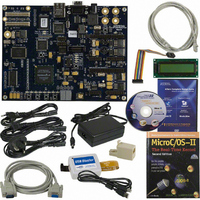
NIOS II KIT W/STRATIX II EP2S60N
Manufacturer
Altera
Series
Stratix® IIr
Type
Nios®IIr
Specifications of DK-NIOS-2S60N
Contents
Eval Board, Design Apps, Software, Cables and Accessories
For Use With/related Products
Stratix ll 2S60N
Lead Free Status / RoHS Status
Lead free / RoHS Compliant
Other names
544-1697
Available stocks
Company
Part Number
Manufacturer
Quantity
Price


The Nios Development Board
1–6
Nios II Development Kit Getting Started User Guide
f
c
4.
Verifying Correct Operation of the Nios Development Board
You will see activity on the board after applying power. As soon as you
apply power to the Nios development board, the Altera FPGA is
configured with a Nios II processor hardware reference design. Once the
FPGA configuration is complete, the Nios II processor in the FPGA wakes
up, initializes itself with boot code from flash memory, and displays
“Nios II” on the LCD for 10 seconds, followed by scrolling instructions
for a web server demo. You can connect the board to an Ethernet network
and view web pages served from the web server reference design.
Verify the following indicators of a properly functioning Nios
development board:
■
■
■
■
■
1
If you are not the first user of your Nios development board, the board
might no longer contain the original factory image programmed in flash
memory. In this case, you will not see the same indicators noted above.
The LED labeled User might be on or flashing, indicating that the
development board is programmed with another designer’s user image.
If you want to reprogram your board to its factory default condition,
refer to the appropriate Nios Development Board Reference Manual.
If this is the first time you are applying power to the Nios development
board and you do not see the indicators above, check all the connections
and make sure that power is supplied to the board properly. For further
assistance visit Altera’s online technical support web site at
mysupport.altera.com.
Connect the DC power-supply to connector J26, as shown in
Figure 1–1 on page
geographic region. Connect one end to the DC power supply and
the other end to a power outlet.
The power LED (LED5) is on. LED5 is located under the Altera logo
near the top-right corner of the board.
The LED labeled “Safe” or “Factory” is on.
The two 7-segment LEDs are active, displaying a spinning pattern.
The LEDs D0 – D7 are active, displaying a bouncing pattern.
The LCD displays “Nios II”.
Connecting the LCD module to any other connector will
damage the LCD module. Do not mistake J12 with the similar
J15 at the bottom edge of the board.
The LCD screen might not function if a CompactFlash card is
seated in the CompactFlash socket.
1–5. Select the appropriate power cord for your
Altera Corporation
May 2007
Related parts for DK-NIOS-2S60N
Image
Part Number
Description
Manufacturer
Datasheet
Request
R

Part Number:
Description:
NIOS II KIT W/CYCLONE II EP2C35N
Manufacturer:
Altera
Datasheet:

Part Number:
Description:
CYCLONE II STARTER KIT EP2C20N
Manufacturer:
Altera
Datasheet:

Part Number:
Description:
KIT DEV NIOS II CYCLONE III ED.
Manufacturer:
Altera
Datasheet:

Part Number:
Description:
KIT DEV MAXII W/EPM 1270N
Manufacturer:
Altera
Datasheet:

Part Number:
Description:
DK-SLSR30-300N EZS RCVR NI HSG 30mm X 300mm NO PKG
Manufacturer:
BANNER ENGINEERING


Part Number:
Description:
CPLD, EP610 Family, ECMOS Process, 300 Gates, 16 Macro Cells, 16 Reg., 16 User I/Os, 5V Supply, 35 Speed Grade, 24DIP
Manufacturer:
Altera Corporation
Datasheet:
Part Number:
Description:
CPLD, EP610 Family, ECMOS Process, 300 Gates, 16 Macro Cells, 16 Reg., 16 User I/Os, 5V Supply, 15 Speed Grade, 24DIP
Manufacturer:
Altera Corporation
Datasheet:
Part Number:
Description:
Manufacturer:
Altera Corporation
Datasheet:
Part Number:
Description:
CPLD, EP610 Family, ECMOS Process, 300 Gates, 16 Macro Cells, 16 Reg., 16 User I/Os, 5V Supply, 30 Speed Grade, 24DIP
Manufacturer:
Altera Corporation
Datasheet:
Part Number:
Description:
High-performance, low-power erasable programmable logic devices with 8 macrocells, 10ns
Manufacturer:
Altera Corporation
Datasheet:
Part Number:
Description:
High-performance, low-power erasable programmable logic devices with 8 macrocells, 7ns
Manufacturer:
Altera Corporation
Datasheet:
Part Number:
Description:
Classic EPLD
Manufacturer:
Altera Corporation
Datasheet:
Part Number:
Description:
High-performance, low-power erasable programmable logic devices with 8 macrocells, 10ns
Manufacturer:
Altera Corporation
Datasheet: