752161473GPTR CTS Resistor Products, 752161473GPTR Datasheet - Page 14
752161473GPTR
Manufacturer Part Number
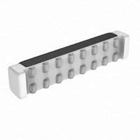
752161473GPTR
Description
RES-NET 47K OHM BUSSED SMD
Manufacturer
CTS Resistor Products
Series
752r
Specifications of 752161473GPTR
Resistance (ohms)
47K
Number Of Resistors
14
Circuit Type
Bussed
Temperature Coefficient
±200ppm/°C
Tolerance
±2%
Power Per Element
80mW
Number Of Pins
16
Package / Case
16-DRT
Size / Dimension
0.465" L x 0.080" W (11.81mm x 2.03mm)
Height
0.095" (2.41mm)
Mounting Type
Surface Mount
Operating Temperature
-55°C ~ 125°C
Lead Free Status / RoHS Status
Lead free / RoHS Compliant
Other names
752-161-47KPTR


www.national.com
Application Information
put ripple. Continuous operation is defined as not allowing
the inductor current to drop to zero during the cycle. It should
be noted that all boost converters shift over to discontinuous
operation as the output load is reduced far enough, but a
larger inductor stays “continuous” over a wider load current
range.
To better understand these trade-offs, a typical application
circuit (5V to 12V boost with a 10µH inductor) will be ana-
lyzed. We will assume:
Since the frequency is 1.6MHz (nominal), the period is ap-
proximately 0.625µs. The duty cycle will be 62.5%, which
means the ON-time of the switch is 0.390µs. It should be
noted that when the switch is ON, the voltage across the
inductor is approximately 4.5V. Using the equation:
We can then calculate the di/dt rate of the inductor which is
found to be 0.45 A/µs during the ON-time. Using these facts,
we can then show what the inductor current will look like
during operation:
During the 0.390µs ON-time, the inductor current ramps up
0.176A and ramps down an equal amount during the OFF-
time. This is defined as the inductor “ripple current”. It can
also be seen that if the load current drops to about 33mA,
the inductor current will begin touching the zero axis which
means it will be in discontinuous mode. A similar analysis
can be performed on any boost converter, to make sure the
ripple current is reasonable and continuous operation will be
maintained at the typical load current values.
MAXIMUM SWITCH CURRENT
The maximum FET switch current available before the cur-
rent limiter cuts in is dependent on duty cycle of the appli-
cation. This is illustrated in a graph in the typical perfor-
mance characterization section which shows typical values
of switch current as a function of effective (actual) duty cycle.
CALCULATING OUTPUT CURRENT OF BOOST
CONVERTER (I
As shown in Figure 2 which depicts inductor current, the load
current is related to the average inductor current by the
relation:
V
IN
= 5V, V
FIGURE 2. 10µH Inductor Current
OUT
AMP
5V - 12V Boost (LM4805)
)
= 12V, V
V = L (di/dt)
DIODE
= 0.5V, V
(Continued)
SW
= 0.5V
20126255
14
Where "DC" is the duty cycle of the application. The switch
current can be found by:
Inductor ripple current is dependent on inductance, duty
cycle, input voltage and frequency:
combining all terms, we can develop an expression which
allows the maximum available load current to be calculated:
The equation shown to calculate maximum load current
takes into account the losses in the inductor or turn-OFF
switching losses of the FET and diode.
DESIGN PARAMETERS V
The value of the FET "ON" voltage (referred to as V
equations 7 thru 10) is dependent on load current. A good
approximation can be obtained by multiplying the "ON Re-
sistance" of the FET times the average inductor current.
FET on resistance increases at V
the internal N-FET has less gate voltage in this input voltage
range (see Typical Performance Characteristics curves).
Above V
to 5V.
The maximum peak switch current the device can deliver is
dependent on duty cycle. For higher duty cycles, see Typical
Performance Characteristics curves.
INDUCTOR SUPPLIERS
Recommended suppliers of inductors for the LM4805 in-
clude, but are not limited to Taiyo-Yuden, Sumida, Coilcraft,
Panasonic, TDK and Murata. When selecting an inductor,
make certain that the continuous current rating is high
enough to avoid saturation at peak currents. A suitable core
type must be used to minimize core (switching) losses, and
wire power losses must be considered when selecting the
current rating.
PCB LAYOUT GUIDELINES
High frequency boost converters require very careful layout
of components in order to get stable operation and low
noise. All components must be as close as possible to the
LM4805 device. It is recommended that a 4-layer PCB be
used so that internal ground planes are available.
Some additional guidelines to be observed:
1. Keep the path between L1, D1, and Co extremely short.
Parasitic trace inductance in series with D1 and Co will
increase noise and ringing.
2. The feedback components R1, R2 and C
close to the FB pin of U1 to prevent noise injection on the FB
pin trace.
3. If internal ground planes are available (recommended)
use vias to connect directly to ground at pin 2 of U1, as well
as the negative sides of capacitors C
I
LOAD
IN
(max) = (1–DC)x(I
= 5V, the FET gate voltage is internally clamped
I
RIPPLE
I
SW
I
LOAD
= I
= DC x (V
IND
= I
(AVG) + 1/2 (I
IND
SW
(AVG) x (1 - DC)
SW
AND I
IN
(max)–DC(V
-V
IN
SW
values below 5V, since
SW
s
) / (f x L)
RIPPLE
1 and Co.
f
IN
)
1 must be kept
-V
SW
))/fL (10)
SW
(7)
(8)
(9)
in
Related parts for 752161473GPTR
Image
Part Number
Description
Manufacturer
Datasheet
Request
R

Part Number:
Description:
RESISTOR NET 4.7K OHM SMD
Manufacturer:
CTS Resistor Products
Datasheet:

Part Number:
Description:
RES .10 OHM 1/8W 5% 0805
Manufacturer:
CTS Resistor Products
Datasheet:

Part Number:
Description:
RES .20 OHM 1/10W 5% 0402
Manufacturer:
CTS Resistor Products
Datasheet:

Part Number:
Description:
RES .47 OHM 1/8W 5% 0805
Manufacturer:
CTS Resistor Products
Datasheet:

Part Number:
Description:
RES .47 OHM 1/10W 5% 0402
Manufacturer:
CTS Resistor Products
Datasheet:

Part Number:
Description:
RES .47 OHM 1/4W 5% 1206
Manufacturer:
CTS Resistor Products
Datasheet:

Part Number:
Description:
RES .20 OHM 1/10W 5% 0603
Manufacturer:
CTS Resistor Products
Datasheet:

Part Number:
Description:
RES .47 OHM 1/2W 5% 1210
Manufacturer:
CTS Resistor Products
Datasheet:

Part Number:
Description:
RES .20 OHM 1/2W 5% 1210
Manufacturer:
CTS Resistor Products
Datasheet:

Part Number:
Description:
RES .47 OHM .75W 5% 2010
Manufacturer:
CTS Resistor Products
Datasheet:

Part Number:
Description:
RES .20 OHM .75W 5% 2010
Manufacturer:
CTS Resistor Products
Datasheet:

Part Number:
Description:
RES .56 OHM .75W 5% 2010
Manufacturer:
CTS Resistor Products
Datasheet:

Part Number:
Description:
RES .91 OHM .75W 5% 2010
Manufacturer:
CTS Resistor Products
Datasheet:

Part Number:
Description:
RES .050 OHM .5W 5% 1206
Manufacturer:
CTS Resistor Products
Datasheet:

Part Number:
Description:
RES NET 15RES 4.7K OHM 16PIN SMD
Manufacturer:
CTS Resistor Products
Datasheet: